Ron Pope Motorsports                California Custom Roadsters               

Complete Rewire Project

I'm not a relay expert (although I play one on TV), but I bet it will carry at least 30A at 12VDC.

Anyway, we took a vote and Indy is nominated to get one and test it to destruction and report.
I had to laugh again when I read your comment about relay expert !!!

I accept your nomination...... With my destructive testing over 7000 mile and 2 years it has not been a problem since 2015 (~2 years).....PotvinGuy(you be right) should we call it acceptable ???
 
Good grief, time flies. I got distracted with new stuff for my front end (in my endless project thread), so the new dash is just a drawing and a pile of parts:
8L55NZPZ0JkWht7URlkK18vf8jSlNwq287CLgIK0-niZhvXtD5s_Qzo1Sh6VC99fXti_EKqDjOwXKHLMbmNT75dmfwNeyZoE12qRaAo5j28QnlqiJcIgr4pHQ-TPPUTPkw78nlx_RmK6gYzVTFfAc-4bAX46G4Mu5DBrMQkXXo_CPHdTmm0n-EXxV9TaRzYSk0tGF6gO_fk53a_lUTEgBDA94gLKCYbOm39FmXLUhNmXuP6RZ4p0FYyr5G_Z7VGbECy0dupceerwfJPW3QAj88jiG2P7ld8J44LOVevEVlCQh6hhaXG7VxwHZncpXJlt62GRqzL8LFm64G1P_WKHyei7rOdFlf9mJdriEztrpq6nkm6bmJAj0Mp07ranFFT3hFFymuxHhQyQ2YIEVovDUi9KCcj0GnyLdI9lkMuhC03XhYGLc1z6owZQHjXa3V7HBHZ4jVDbh0ckFJFH7139v1o0a9bFqtttyxfe0qxjoPni5r3DY8keyok258G24XeMp1A-MsOx4AJlXqP4n5hXh2tPnYHwNdy-J9RqMJyjTtAdTKBZLK0T12cidj2Cj9wIZNQxJ_K-_4HEyo84fTUF1RDNgfmUIwNYzKfppV46iBZcgxCw-bGL=w820-h615-no


Still have a month here before the cruises start and have a few issues on the car to sort. Going to Des Moines GG and Speedway/Lincoln this year.
You have done well, young skywalker. Consider the relay man-rated and flight-ready.
Got any pics of the dash and such?
 
I'm leaving tomorrow for a NTBA event in Nazerath Texas where the 2nd largest canyon in the US is located. It's a 5 hour drive to get there.

I have not got around to building the new dash from the exotic wood, but there are some pics on pages 8 & 9 of this thread for the pine wood dash.
 
I'm getting tired of remembering to flip the switch off when I'm coming to a stop. The car
bucks a little bit then down shifts and bucks a little in each gear if I don't flip the switch.
Except for 1st gear, it's impossible to lockup in that gear. So, I got an idea to use a latching
relay to keep the TC lockup engaged until I tap the brake pedal.

Last time I replaced the brake switch I ordered one that also has normally closed (NC)
contacts that is typically used for cruise control. I will use this to dis-engage the TC by
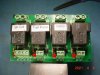
opening those contacts when I tap the brake. Of the two relay boards (4 relays each)
installed now, I have one relay that is not being used. This will become my latching relay
after I modify it by simply adding a wire from pin #85 to #87.

FP02_RelayModule_02684.jpg


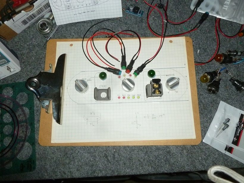
To engage the TC I will use a "Momentary Push Button Switch". Then the latching relay
will stay on, keeping the TC locked. When I get off the highway and tap the brakes, the
brake switch will de-energized the circuit by removing the ground.

upload_2021-4-6_16-37-10.png

Cooling,FuelPump,Horn&TCC_06.jpg
TC_LockupDrawing02.jpg

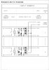
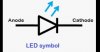
I’ve noticed that many times a diode is used to block the voltage spike when the magnetic
field collapses. The diagram for my relay module is shown below.

I’m wondering if someone can tell me what function the diodes in the diagram below
are performing.

Omron-Relay-Module-5.jpg
.
 

Attachments

  • FP02_RelayModule_02684.jpg
    FP02_RelayModule_02684.jpg
    192.5 KB · Views: 3
  • Omron-Relay-Module-5.jpg
    Omron-Relay-Module-5.jpg
    66.2 KB · Views: 2
You might check with Bowtie Overdrive. Their transmissions are wired to lock up the torque converter automatically, and you use a normally closed relay wired into the brake light circuit to disengage.
 
The extra diodes are there to isolate the individual inputs from each other and the common control busses.
Do you have a link to the relay module? It's been a while since I used one and I'd like to refresh my spotty memory.
For some reason I don't get emails of new posts so I have to check daily and scan the forums.
 
Do you have a link to the relay module?
When I checked, they didn't sell mine. But there were lots of other that looked identical
except for the color on Amazon.
 
I'm trying to get my latching relay to work, but everything I have tried has failed.

Can anyone point out what is wrong ? Should I use a diode for my jump on pins 85 to 87 ?

Changes.01-DidNotWork.jpg
.
 
Maybe I should include the drawing for the LED switch. Here it is ....

ApieleMomentaryPBSwitchDiagram.jpg
 
Indy, which button diagram (1-4) are you using?

I've redrawn your wiring:
Indys lockup trans.jpeg
If this is correct a) the relay probably won't latch, and b) the trans will only get a momentary ground when you press the button.
Let me know how the button is supposed to work (what is the light supposed to do), and I will respond with a suggested wiring as soon as I finish sorting my socks.
 
I want the ring light (Mom Switch) to be on when the TC is locked. To deactivate the TC will be the NC
contacts on the brake light switch that open when I brake.

How many socks do you own ??? :eek:
 
This should do the trick:
indys new circuit.jpeg
Normally the relay is off, the LED is off and the TC is not locked. When you press the button the relay is energized and locks thru it's contacts. At the same time the TC locks and the LED is on. When the brake is pressed the relay drops out and everything goes back to normal. Note the wire colors on the button. The yellow wire is not used (it's the NC side of the button).

Socks...well, if we include the pantyhose and the fishnet nylons...ah, maybe 3 drawers, tops.
 
I see "12" in 3 places, I assume that's 12 volts ? Can I run those 3 wires to the fuse panel and thru a fuse ?

You also added a diode, I have several 1N5402 diodes, will they work? What a minute, that light inside the momentary switch, right ? That's one of two blue boxes. Then the relay is the other blue box ?

1N5402 Diode Pinout, Datasheet, Equivalents & Features

You the man Mr Panty Hose !!! As long as you have answers, I don't care where you put fishnets !

You should confer with IG, she might have some tips to make your life easier !
 
If your using a good efi or electronic ign., you could actually use your ign. or efi to trigger your lockup, using the signal to trip your relay or module. IE, engine vac., rpm, etc....
I have used the brake line stoplight switches to kick them off....
 
If your using a good efi or electronic ign., you could actually use your ign. or efi to trigger your lockup
Nope, just using my 750 cfm, Vac Sec carburetor and MSD ready to run distributor. But that
does make me think about my AQ-1 data system ......hum what could I do with that ???
 
I see "12" in 3 places, I assume that's 12 volts ? Can I run those 3 wires to the fuse panel and thru a fuse ?

You also added a diode, I have several 1N5402 diodes, will they work? What a minute, that light inside the momentary switch, right ? That's one of two blue boxes. Then the relay is the other blue box ?
Yeah, switched 12 for all 3, same fuse OK. The "diode" is the LED in the button. Sometimes an LED is shown as a diode (which it is) with a little squiggle or arrows near it indicating light, but the squiggle isn't always there.
LEd 2.png
You know, I don't like to spread rumors, but the fishnets came from ORF after a night of drinking at the last T NATS...I think.
 

Attachments

  • LED symbol.jpg
    LED symbol.jpg
    13.6 KB · Views: 2
Last edited:
Yeah, switched 12 for all 3, same fuse OK. The "diode" is the LED in the button. Sometimes an LED is shown as a diode (which it is) with a little squiggle near it indicating light, but the squiggle isn't always there.
OK, tomorrow I will try rewiring again and report my findings.

You know, I don't like to spread rumors, but the fishnets came from ORF.
It's not a rumor if my name is not included in the rumor !
 

     Ron Pope Motorsports                Advertise with Us!     
Back
Top