Ron Pope Motorsports                California Custom Roadsters               

Scratch Built Wishbones

RexRod

New Member
Hello all!

Well, the economy is tanked and I've been without work since mid December of last year. Yikes! I have to admit, I'm starting to get a little worried about it. I can't sit around and cry like a baby while the powers that be try to figure out this darn mess. Besides, I'm getting bored, and I'm nowhere near ready to retire.

I don't feel financially safe enough to start gung-ho on my own project, but it did occur to me that I could start making bits and pieces. A few days ago I started to think about radius rods and made a post about their lengths. I figured that would be an easy and simple project for me. Something to cheer me up!

A little background
==============

The radius rod length thread got me thinking again about the possibility of using a set of traditional wishbones instead of hairpins for my future project. With great interest, I've followed wishbone sales on Ebay and the Hamb for about six months. I keep thinking, “Wouldn't it be cool to use real wishbones?” Anyway, the radius rod lengths post made me ask myself, “Why not build them?”

Because I have more time then money or sense, I'm starting my first build thread. It's not a “Whole Car” build thread like the rest of you, just a small part of it. I would like to design and build from scratch, a set of front and rear traditional looking wishbones. I want them split in style and inspired in appearance by the man himself, Henry Ford. I even have some ideas on how to make them stronger than the originals.

I'm not sure if this exercise will amount to anything of value, or if I'll even succeed at it. The worst that will happen from my efforts is I'll have a lot of fun and possibly a cool set of hand made wishbones. And in the spirit of a true build thread, mistakes will be made and directions will change. I also don't claim to know much of anything, even though I'll try and convince you otherwise... (it's all part of my master plan Bwahahahahah!). It seems like the older I get and the more I learn, the less I really know! Feel free to thread jack and mind dump. This thread is all about sharing ideas.

Lets get started. I've been looking at different styles of Ford wishbones from photographs (I don't actually have any real ones). Here are some thoughts about what I want them to look like:

Front brackets
===========

Hands down for me anyway, the 32 style offset front bracket mount is my favorite in appearance. This is the front bracket I'm going to use as a model for my front wishbones. Here is a photo I stole from the Web to illustrate what I mean:

32Ford2.jpg


I love the look of the bottom part/line of the bar being lower than the rest of the bracket. I am a huge fan of the traditional looking rod, and from my lurkings on this forum and others, I especially like the look of cars that are built as low as possible. I think a wishbone front bracket that places the bar low, relative to the front axle mounting, should make for a more horizontal looking bar. I also plan to make the opening of the bracket mouth 2 1/4" to fit the more modern after market I-Beam axles.

Caster
=====

I've researched the caster in these front brackets. I've read threads that put the solid front axle caster between 4 and 9 degrees. I also found a source that quotes a 36 Ford manual saying set the front caster to 8.5 degrees. I'm thinking that something between 6 or 7 degrees would be good. Of course, caster will ultimately be determined by how horizontal you can mount the bar at the frame end. I'm just trying to come up with a number for the bracket. What about 7 degrees? Anyone here who knows anything about this and has some thoughts, please chime in!

From the photographs of the 32 front brackets, I guesstimate the angle to be something between 7 and 8 degrees (visualize old bald guy with protractor pressed up against his computer monitor).

Bar width looking down from the top
===========================

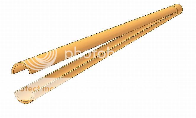
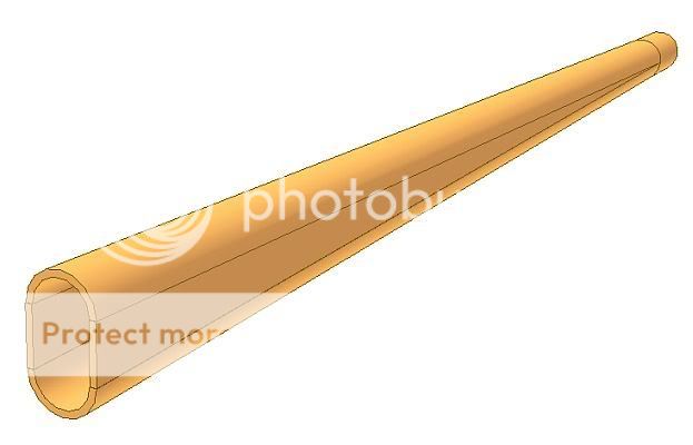
The next thing I'm hoping for is some feedback about the width of the bars, looking down at them from the top. They all taper from a taller oval up front, to a round shape out back, looking at the sides. But what I'm talking about is the width of the bar looking down on it. The later 40's style wishbones are much heavier/wider looking from the top, probably because the cars where starting to get pretty heavy. I want to make a bar that is strong, but I don't think the look of the wider, later model bars is right for our little cars. I also know that some wishbones (the Model A I think, not 100% sure on this) change in width from the front to back, looking from the top. Narrower up front, then they get wider at the back, as their height tapers down to a round shape. Here is a really crappy picture I found. Unfortunately it's not very clear:

taperedwidth.jpg


It's hard to see this in the last image, but the bar is much narrower from the top at the axle end compared to the back end. I've seen this up close on cars at shows. I personally don't like the look, but again, that's just me. I'm going more for constant width from front to back, looking down. (Note: I hope all that made sense. I don't want you to confuse it with the beautiful taper of the bar from front to back looking at the sides.)

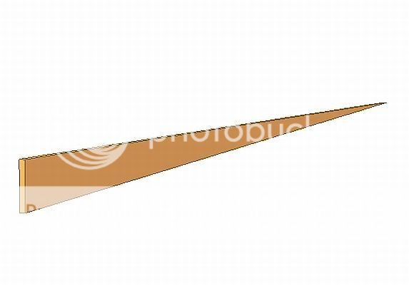
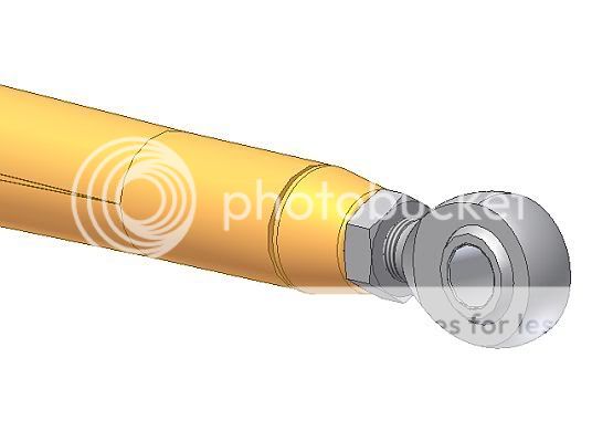
EDIT: I found a slightly better image of what I'm trying to talk about. Here it is:

taper1.jpg


You can see how much wider the bar is at the back relative to the front from the top.

Final note on bar width: I will definitely go for a heavier/wider bar for the rear. Especially because the rear bars are much longer and they need to handle the torque from a more modern engine.

Rear Bracket
==========

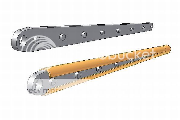
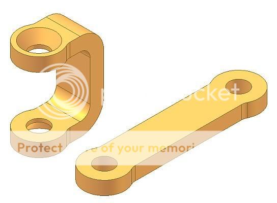
I found what I think is a great looking rear bracket to interface with the rear axle. I think it's from a 35-36 Ford. What I like is it mounts the wishbone bar to the bottom of the axle. Again, this type of setup should help when you're trying to keep the frame as low to the ground as possible. I want my rear bracket to be inspired by this design. It looks something like this:

36Ford.jpg


What ever final style I come up with for the rear bracket, I'm going with some kind of below-the-axle mount to keep the bar as low as possible.

How long
=======

I'm shooting for a working length of 42” to 44” for the front wishbones and 60” to 64” long for the rears. From what I've gathered from the Web, this seems close to the real deal. Feel free to comment on length.

Well, that's it for now. Tomorrow, I'm going to try and extract some dimensions from the dozens of photographs of wishbones I've stolen off the Web over the last six months. There are also a couple of shops in the area I can visit that might have some real wishbones I could steal dimensions from.

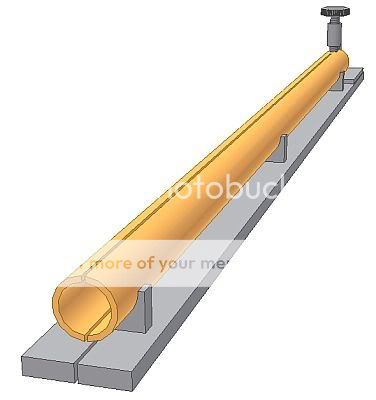
I spent some time today down in my shop gluing up a few strips of MDF to start making a wooden prototype. That'll help me see if I'm even getting close to something real.

Thanks everyone for your patience on this very long first post. Take care,

David
 
I like the look of wishbones better than hairpins too. My car is going to have to wait a little longer than I wanted it to also, but in the meantime I have been collcting pictures and getting ideas. I have given some thought to building my own, not as much as you have, but some. I haven't given any serious thought to how, but I was wondering if it would be possible some how to build a camber adjustment into them. This will be an interesting thread to watch.

This cought my eye, I like the wishbones, and the body from the windshield back has possibilities.
IMG_1531.jpg
 
ok dave...let talk 'bones for a while.

front wishbone.........

i don't have a '32 piece here ('33, '34 would be the same) but i do have a model A piece. major difference between the two is the dog leg you like. if you cut the forging off at the weld on the back end, you will have a 34" 'bone from the clevis to the cut (31" of tube).

the tube itself is akin to a length of tubing that has been flattened at one end to a 1" X 2 1/4" oval (the clevis end) and 1 1/4" round at the other end. so basicly you have a 1 1/4" tube. thus the tapers you were talking about. the wall thickness is .125. when henry made his, the tube was formed and wielded, then the forgings where added. the forging slip inside the tube about 2 1/4"at the clevis and about 1 1/4" at the rear joint.

the spring perch pin is at 4 degree from the top of the tube. the rest of the caster would be determend buy the rear mounting.

just a note about the dog leg here. it was added for two reasons. one being the 2"axel and the other was for pan clearance for the new V-8.

rear 'bones...............

the pieces you have pictured are from a '35 or '36 ford pass. or p/u. i don't have one here to give you the measurements from. however, the first time i used those bars, i replaced the original tubes with ones from the front 'bone from a '40 because of the wall thickness, .125 as opposed to .094.

a word of caution here, these bars used with anything over say....200 horses have a tendency to break at the rear forging/tube joint. originally
these were designed to be used with a torque tube sharing the load. also, if you are using these or any ford bone, remove the factory wields and re-wield them. these wields were made bare wielding rod ( no shielding) and are full of gas holes.

the set don has on his beautiful lil t are from a company called P.S.I. they are no longer in business. don could give you the specs on this set up.

builders tip...for those building to a back in the day theme...the forward end of the rear bones makes a cool lower shock mount on the rear of your car.
 
that's a cool concept martin....looks like a cross between a boydster and an el camino ..... sorry anything with boyd connected to it gets by-passed here.

Ron
 
Thanks everyone for the responses!

Ron,

Thank you so much for sharing some facts about wishbones. My problem is I don't have a collection of real bones here for me to chop up and examine. So I'm flying a little blind. I will correct my original post to reflect some of the dates you mention.

I also was thinking about the drive shaft torque tube being an extra arm, so to speak, in the system for the rear. Increasing the arm strength will be one of my biggest challenges.

One of the ideas I have is to make the height of the arm a little taller at the axle end. You say the oval part of the front Model A arm is 2 1/4 inches high at the axle end. I could make mine 2 1/2". Maybe for the rear arms, I make them closer to 3" high at the axle bracket end. I don't want to go too high, because it would change the character of the look I like so much.

A second idea I'm kicking around is using a heavier wall for the outer tube of the arm.

My third idea involves putting a third vertical piece straight down the center of the wishbone. Here is a really rough cross section sketch of what I mean:

cross.jpg


I have convinced myself (HA!) that I'll be able to use a solid steel "Buck," or I guess the correct term would be "Hammer Form" to form the outer sides of the arms, then make a third vertical center piece/web like shown above to add stiffness. The pieces are then fit together so they all become one unit when welded down the top an bottom of the arms. It should be easy to grind off the weld later for a nice smooth look.

The center piece could even be made from something pretty heavy like 3/16" sheet for the rear arms. This should help take a lot of the torque seen on the arm (I'm no engineer here). For the front, the third vertical piece could help preserve some of the structural integrity of the arm for those who want to drill the sides to mount spring shackles (every time I see someone do that with original bones, I cringe with fear).

I plan on destroying one of these as a test. I'll need to build something to compare to. Maybe one of Pope's arms. His arms are built so tough, something like that would be a good thing to make a comparison with.

Again, thanks for all the thoughts! I'll make an update when I've gathered some more dimensions.

Take care,

David
 
your idea of the 3 piece is a good one. the piece of mat'l in the center has been done before to a stock rod. i have seen a set that had the wield removed and holes drilled on the opposite side. a 1/4" plate was then set in the tube and plug welded on the top and re-wielded on the bottom. with your 3 piece design, you could go one step further and wield the plate to the ends first and then wield the outside pieces.

now for the other thing you touched on, drilling the rod for spring perches. you can stop cringing dave. there are no less that 8 cars out there with this very front end on it that i have built. the oldest one was done in '69 and i would guess has in the neighborhood of 100,000 miles on it with no problems. the car was run at twin city and minnesota dragways for 3 years and was known to lift the front wheels very often. the last set up like this is in the post of the model a chassis i finished a while back. the only variation was that because i used the '35 front end with a 31" spring, i couldn't use the model A spring perch.

i found a '46 rear rod in the shop and it is also 1 1/4" at the round end. the oval end is 2 1/8" X 1 1/2" with a .094 wall thickness.

you talked of increasing the 2 1/4" to 2 1/2" or 3". i don't think that would be necessary. if you were to go to 2 1/4" X 1 1/2" with the extra center plate wielded to the ends you should be good to go. jmo

once again, i can't stress enough....grind out the factory wields and re-wield if you are using stock ford bones!!!!!

Ron
 
Youngster said:
now for the other thing you touched on, drilling the rod for spring perches. you can stop cringing dave. there are no less that 8 cars out there with this very front end on it that i have built. the oldest one was done in '69 and i would guess has in the neighborhood of 100,000 miles on it with no problems. the car was run at twin city and minnesota dragways for 3 years and was known to lift the front wheels very often. the last set up like this is in the post of the model a chassis i finished a while back. the only variation was that because i used the '35 front end with a 31" spring, i couldn't use the model A spring perch.

Well, I stand corrected then. To me it seems too weak, but I will trust your experience. I have a long and irritating reputation to others for being a bit of a scaredy cat when it comes to stuff like this.

i found a '46 rear rod in the shop and it is also 1 1/4" at the round end. the oval end is 2 1/8" X 1 1/2" with a .094 wall thickness.

you talked of increasing the 2 1/4" to 2 1/2" or 3". i don't think that would be necessary. if you were to go to 2 1/4" X 1 1/2" with the extra center plate wielded to the ends you should be good to go. jmo
Ron
I like what you're saying. I would very much prefer to keep the over all height of the arm at the axle end shorter. I'm concerned about the appearance of 1 1/2" being too thick at the top though. I have some 1" X 3" and 1 1/2" X 3" MDF strips glued up. I'll try an shape up some arms to see how they look. Maybe 2 1/4" high by 1 1/4" wide at the axle end, that tapers down to a round 1 1/4" is a compromise? The sides I wrap it with will be much easier to make if the width of the bar is the same from front to back.

You also mentioned a full 1/4" thick center vertical put into an original wishbone for strength. Now that I bet is super strong! If I used a full 1/4" thick center for my part, it would allow me to use the thinner .125" for the outsides (much easier to cold form!). And you're right, my idea was to weld both ends together to the center vertical before I wrap it with the sides.

Thanks for taking these measurements Ron.

David
 
glad to help dave....one suggestion....find an A wishbone before you go too far for refrence....could answer a lot of the cosmetic questions you have. please keep us posted.

Ron
 
Since you have asked for ideas on how to go about making some "Bones" , I'll throw out some stuff that your request made me think about.
I will start off by saying that I was thinking of this in the context of working within my capabilities as far as equipment and access to industrial processes goes. I have no idea how much you have in resources in these areas.
For me, the idea of forming the radius over a hammer form looks like a lot of hand work and would be hard to get consistent results. The alternative might be to press the form and blank into a urethane or rubber female die but that would require a very large press and lots of force. I would take the road of using an already formed radius by way of using round tubing as a basis for this exercise.
We just need to split the tube for nearly the entire length to have 2 parts with the radius that we desire. The reason for leaving the short end of the tube uncut is that it will make subsequent operations easier and will give a true diameter for adding the adapter for the rod end or tie rod end. Based on some of the dimensions that you have mentioned, I chose to use 1-1/4" x .120 wall tube. These are not set in stone dimensions, they can be altered easily.
Bones-TubeFormed.jpg

This split tube is what I am trying to achieve. To get a good straight cut for that much length is a bit of a challenge. I think that I would make a guide for holding the tube and making the cut.
Bones-TubeJig.jpg

After the cut is made, the next problem is to get the tube to match the flared shape of the original style. Another helper tool might come in handy when trying to do this on a consistent basis. This is a piece of bar stock that is cut so that the taper matches the inside of the tube wall. It should spread out the two sections of tube and provide a clamping support if things get a little different than expected. The holes and pins match in length the inside dimension of the wedge shaped inserts. They locate and support the wedges and provide a clamping spot while you get them tacked in place. The smaller surface area that contacts the wedges should help in removing the bar.
Bones-TubeGauge.jpg

The wedge pieces could be sheared pretty easily but sheared pieces this small have a tendency to twist over their length. It would probably be better to have them laser cut and maintain the flatness.
Bones-Wedges.jpg

After everything is clamped, checked, tacked and welded, hopefully I would have something that looked like this.
Bones-TubeWedges.jpg

The other end of the tube would get an adapter for the rod end or whatever fitting that would be appropriate. By inserting it and welding it now, you have something to hook onto in case the tapered jig doesn't care to slip out very easily. That is the purpose of the big hole in the end of it also.
Bones-RodEnd-1.jpg

For the Clevis end of the Bone, I would have them laser cut from 1/2 plate. The laser gives accurate parts that as dimensionally correct to a couple of thousandths of an inch. They also make cuts that are vertically true in material that is this heavy. I would leave the chamfering of the hole until after the forming operation to avoid any distortion from the bending. The bending could be done in a press with a piece of tooling that would locate both ends from the same locators so that the hole centers would be colinear when the bending is complete.
Bones-ClevisFlat.jpg

The end of the tube can now be trimmed to match what has been chosen for a castor angle and the clevis welded in position. If all went as planned, I should have something that looks like this:
Bones-CompleteUnit.jpg

If you should choose to use any or all of these ideas, I hope that you have as much fun doing it in real life and I have had in doing it in cyberspace. :D
 
Wow George :clap:. I am always amazed with your posts. Very well explained and the cad work is awesome. Thanks.
 
GAB

I thought you might in fact be the George Barnes of Tubular Dynamics. I have know of you for a number of years. In fact, I think you bend some tube parts for a friend of mine in KC. His name is Dick Kitzmiller of Scarab Motorsports and you might still be bending their parts.

I to have thought about building radius rod strickly for personal use. The idea of splitting a tuge is a good one. One way to get an accurate cut that long would be to use a water jet. As you know, it would pierce both walls of the tube leaving a very clean and uncontaminated edge. With proper fixturing I really don't think you would need to have the inserted machined piece. You are right on with laser cutting the clevis and forming it. To bad all this technology wasn't around years ago. No telling what we would be building today. Then again it would probably be the same type cars. Some boys just never grow up.

George
 
George, (GAB)

You are amazing!!!!!! I wish I had your CAD skills. I could I guess if I just spent the time to learn how. I must be lazy. :lol:

I wish you lived closer to me. Everytime you make a post, I get blown away. I would love to see your space and what you're working on.

In response to your post, I had the same idea earlier of splitting a length of tubing as well. I chose to pass on it for my first try because it doubled my welding. Four full length seams instead of two for each bar. If my forming idea of doing it in two halves doesn't work out though, I'm definitely going to do it the way you mention above. Making that long radius look good is key, and the split tube idea would really make that happen.

I did try and pound a short length of 11 guage over a piece of 1" round 1018 and I was suprized at how well it went. I found that a large Nylon faced dead blow hammer I have was the best tool to use. Leaves no marks and creates bends real slow and gradual. I'm thinking this is the key. A steel hammer just made everything ugly and uneven. I'm feeling optimistic. :lol:

I spent most of the weekend working out final dimensions for my front and rear wishbone designs. With everything comes compromise, and I've already deviated a bit from my original ideas. When I have more to show, I'll let everyone see. I'm going to try and make my front brakets first. Your front bracket idea is super clean and easy to make. Very nice idea, but a little too plain for me. I've got an 18" long chunk of 2" by 4" 1018 bar stock I found in my junk bin I'm going to try and use instead.

HA! Something tells me I'm going to spend more time on making these wishbones than it takes to make a whole chassis!

As far as my abilities, I'm more of a machinist than a fabricator. My workshop here at home is modest, but I do have the basics, just enough to get into trouble. :eek:

A short list of the most important gear:

For fab, I don't have anything heavy for bending stuff, but I do have an OXT/ACT set for hot bending small parts if needed. I have TIG and MIG here as well for making stuff stick together, and I do a pretty good job of fooling everyone around me that I know what I'm doing. I have two nice older DoAll saws for cutting stuff off. One 10" horizontal, and one three wheel vertical with a 36" throat.

For machining I have one great older 14" by 54" lathe that seems to do just about anything I need that's round. I have two series one, universal knee mills (think Bridgeport), one retrofitted with an Anilam two axis CNC controller, so complex shapes are not a problem. A small heat treat oven and a 6" by 18" surface grinder for tool making. I've got more, but you get the idea. For being only a home shop, I feel super lucky and thankful to have the kind of space I do. All I really need is some more room......

Thanks again for the input. Take care,

David
 
awesome post as always george(GAB). the problem i can foresee is when cutting the tube it's going to bow away from the cut. hand forming these could give the same problem. having the pieces formed on a break press will nearly eliminate this.

if i had manufacturing in mind, i would definately look at having the pieces formed on a break press along with assembly fixtures.

at this point if i where looking at a onetime fab, i would hand form the two pieces and assemble as dave first posted. 10guage forms fairly easy with simple tools(bfh). i would think about using a stock clevis even to retain the original feel.

Ron
 
fluidfloyd,

Yes, I know Dick Kitzmiller. The only thing that I have done for him is a few bends for the back of the Scarab prototype. He has been over here several times to talk about doing some things but nothing has materialized yet.

The Scarab is quite a project and they have done an excellent job on it. I have a cousin whose son is doing the electrical part of it.

rexrod,

It sounds like you are pretty well equipped for building stuff.

My shop is a conglomeration of worn out and homebuilt junk. :lol: I'm afraid that you'd be disappointed in what you would find if you dropped in here. Not much in the way of trick stuff, mostly just boring old production stuff. But when I started 34 years ago, I soon learned that production pays the bills and custom stuff is for feeding the ego. It's awfully hard to charge what custom work requires in labor. Seems like I end up eating half of it and it don't taste that good.:lol:

Having warned you guys about what to expect, anyone is welcome to drop by and I'll be happy to give you the nickel tour.
 
GAB do you have the capabilitys to make the ends for those rods? I was talking to a guy who has a waterjet and he says it would not split the tube both sides at once. Only one side at a time. I think we can set up our plasma cutter to split one side at a time, rotate it 180 and split the other side.
 
GAB,

I seriously doubt your homemade gear is junk. And a good machinist can make perfect parts all day long on a worn out machine. All of my gear is old and VERY used. I would feel very honored to meet you someday.

RPM,

Your plasma machine would be perfect for splitting those tubes! It would also be able to make that long thin taper as well. :cool:

D.
 
GAB said:
fluidfloyd,

#1 Yes, I know Dick Kitzmiller.

#2 My shop is a conglomeration of worn out and homebuilt junk.

#3 I soon learned that production pays the bills and custom stuff is for feeding the ego. It's awfully hard to charge what custom work requires in labor. Seems like I end up eating half of it and it don't taste that good.:lol:

GAB,

#1 The tubes you bent for Dick were probably for his first attempt to build the proto car in house. He contracted me to build the 1st proto chassis right as I was moving to Arkansas. He brought those tubes with him but he had already welded them together and the bends wouldn't align using the C5 Corvette components. He then decided to go ahead and build it using 4130N like the original cars were constructed. I build the first chassis and suspension components here in my Arkansas shop. Dick brought down the aluminum body and he, his friend and I mounted it. They had it painted here by a local hot rod type guy and then took it back to K.C. to be finished. I think that was done by your cousin's son and his friend and they are probably doing the production cars. The car really turned out nice and they have about 8 more sold. They just got a final weight on the car and it sits ready to run less driver @2180lbs. I figured it would come in under 2300 so I'm pleased. If anyone would like to view this car then they can go to: www.scarab-motorsports.com

#2 All my equipment is like me, old and well used. All manual controls except for the CNC stuff. Probably the same as yours...Crank 'N Cut. All heavy iron. Smallest lathe is 4000#. Big saw 5000#. Old Lincoln Tig machines. Hossfeld tube bender. Only thing new is a used laptop and early Autocad and Solidworks. I'm still struggling with Solidworks.

#3 Yep! I understand that well. Maybe I'll be in K.C. again and if I am I'll call you.

What modeling program are you using and what version? Thanks for the response.

George
 

     Ron Pope Motorsports                Advertise with Us!     
Back
Top