Ron Pope Motorsports                California Custom Roadsters               

Attempting and English Wheel

RexRod

New Member
Not T-Bucket related, again, but....

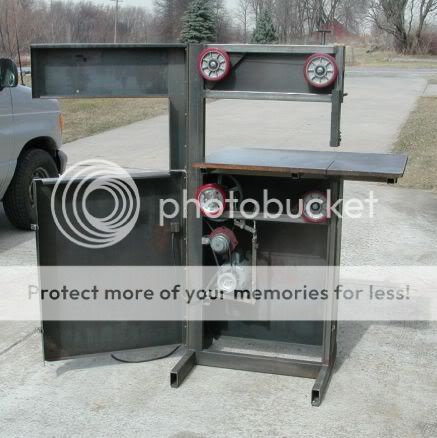
More than 10 years ago, I started building an English Wheel. Well, that project got put aside when life got into the way, and it has been sitting under a tarp in my yard ever since. :sad: So I dragged it out of the yard up onto the driveway a couple of weekends ago to have a look. Somehow it looks bigger than I remember it. :eek:

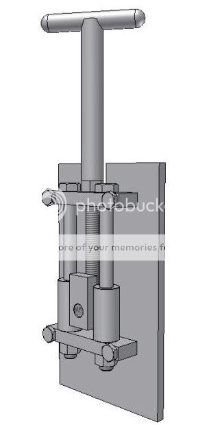
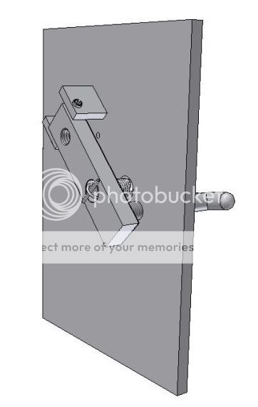
In about two weeks, I will be finished with the bits and pieces I used to make in my spare time, and one of the first things I am going to do is finish this tool up. I designed it to be extra beefy so it might also do things like punch louvers, and maybe even shrink and stretch with some special dies I have floating in my head. I might even make a bead roller attachment for it as well. Space is a problem here, so multiple tools-in-one are a good thing! ;)

Should I do a write up in the "Shop Tools and Tricks" section? It's not the easiest thing to build, and probably not a very popular tool when most people here use glass for body panels.

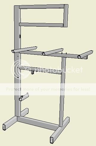
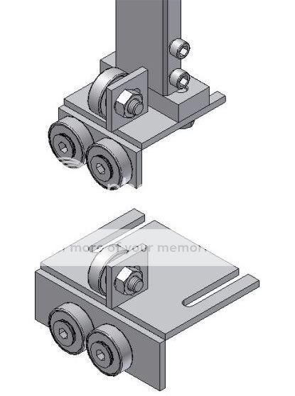
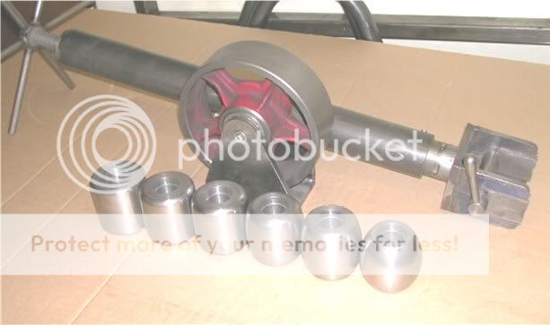
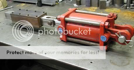
Here are some pictures of the bare frame:

wheel1.jpg


wheel2.jpg


Just so you have some idea, the face verticals are 4" square by 1/4" wall, and the sides are flame cut from 1/2" A-36 steel plate. I even put some extra backbone inside made from 8" by 7" I-Beam. The throat is 38" (36" working) deep.

The first thing I noticed is it's a bit short. I might rework the legs to raise it up another 8 to 10 inches. Oh, the reason it's too short? I started building it without ever standing next to a real English Wheel. I started it from seeing other wheels in pictures (I am a much better planner now :cry:). When I finally got to use a Wheel, I was surprised how high the working sheet height was. I guess it's so you don't fatigue from slumping when wheeling. ;)

I need to take a wire wheel to it and try to grind off years of corrosion from it just sitting in the yard. Especially on the bottom!

Just sharing what I'm up to. Take care,

David
 
Very nice wheel :cool: By all means do a shop tool writeup.
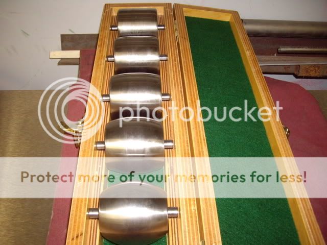
 :cry:
 
That is one serious piece of equipment there, you won't have to worry about it deflecting under pressure. :cry: I like it, especially since you are making it to do several different tasks.

Yep, please do a tech article on it.

Don
 
Thats Money $$$$$ in the bank when you get it set up and figger out how to use it......
You could roll fenders for these guys that are required to use em.
Punch Louvers in rear deck lids, hoods on these "Track Cars", lots of things.... You could make up a tear drop forming punch and form some tear drops over steering arms and clearance for valve covers, all kinds of stuff.
You have a good solid frame there from the looks of it, hang in there and keep those brain cells workin ! LOL
"BH"
 
I would ask you to please post an article. The fact that it is a multi purpose piece of equipment is a huge plus. Chances are there are more people out here with something (cough) similar in the making. From your other posts, I would like to see how this progresses.

Ron
 
Youngster said:
I would ask you to please post an article. The fact that it is a multi purpose piece of equipment is a huge plus. Chances are there are more people out here with something (cough) similar in the making. From your other posts, I would like to see how this progresses.

Ron

Will do. But it'll be more of a "Build Thread" than a single post with every detail in one shot in the beginning like most of the other posts in the "Shop Tools and Tricks" section. Way too big of a project for a one shot. It's also nice that people will be able to make comments like everywhere else in this forum. It'll make it more interesting. ;)

I will start the thread with pictures and details of how I built the basic frame for the machine, when it's done of course. Then I will add to the thread showing how I make the parts for it to be an English Wheel. After that, each additional component adapted to the basic frame will just be an added post to the same thread.

I will start as a tool builder. :cool:

Thanks for the complements people!

David
 
Looks a lot like a Pull Max machine to me. With the right dies and some practice you can do amazing things with those.
 
I'm hoping Dave goes that way Martin. I have a couple of '32 Ford type pick up boxes to build.The beads are wider than any dies I've been able to find for my bead roller. I'm playing with the idea of using an air hammer with dies in the frame I built for the bead roller.
Ron
 
Hi Dave,
It looks like you are off to a nice start on your English wheel. Do you know what size and taper youre going to machine your wheels to? If you need some info let me know and I can measure mine. I'm in a similar situation, I bought a kit a couple of years ago but havent had time to make the frame yet.
IMGP5265.jpg


Ron,
I have a bench top power hammer that I could take some pictures of if you like. The dies are the most important part. It will shrink and strech both. If you need to use it, there might be a chance I could bring it with me when I pass by your place in a couple of weeks. Ill be north of you for 5-6 days and could pick it up on the way back home.
Bill
 
Bill Pedersen said:
Hi Dave,
It looks like you are off to a nice start on your English wheel. Do you know what size and taper you’re going to machine your wheels to? If you need some info let me know and I can measure mine. I'm in a similar situation, I bought a kit a couple of years ago but haven’t had time to make the frame yet.
Bill

Hi Bill,

Looks like you bought a nice set!

It's actually not a taper on the wheels, but the width of the flat in the center with a radius on each side of it. At least, that's what Ron Covell taught me. The smaller the radius, the shorter the flat in the middle. If you look closely at your wheels, you will see it.

I may have mentioned this before, but I had the super good fortune to take a two day workshop with Mr. Covell at Pinkee's Rod Shop. That's where I finally got to see in action a ton of different coach building tools, including a PullMax. The PullMax is a MONSTER compared to my machine. :eek:

I thought originally when I started my machine, that it would be nice to form in the middle of a large panel. That's why I made the throat so deep. Maybe some kind of forming hammer head attachment would be practical. I would have to think about how I would drive it. I know how the PullMax drive works. What I don't like about the PullMax is the cadence of the tool. Way too fast for me.

Keep the ideas flowing!

David
 
Bill...If you could take a few shots of the power hammer that would be great. Now ya got me goin'. What could I form in a few days? The cowl flare for my dirt tracker, A blister for the cowl steering on my '27, an Indy type nose for the T bucket.....I gotta go make a list!

Actually, what I have in mind is a male upper die and a female lower one to make a 1-1/4" bead about .125" deep.

Ron
 
I too had started an Wheeling machine at some time in the distant past, only to be struck with the idea that a Wheel and a Louver press shared a lot of characteristics. I had made my upper wheel, adjuster, and a set of anvils when this revelation occurred.

Ewheel1.jpg


I had most of the rectangular tube cut and was about to start to weld it together at that point. I was building to the John Glover plans that came from Sport Aviation. I had decided that the plan was to make interchangeable heads for the two machines.

LouverPressSlide002.jpg


I started to make the louver press parts by shortening a hydraulic cylinder and making a slide for the upper die mount. That was as far as I got. When you are self employed, the choice of whether to do your own stuff or paying stuff, isn't much of a choice. Self discipline is what they call it, I think. :)

This thread is interesting to me as I have been wondering if there were anybody on this board that was interested in tool plans for some of the more robust pieces of equipment. A lot of the equipment in my shop is home built stuff. I've done quite a bit of 3D drawing on a lot of them. They are not complete plan sets as such, but a little studying should answer most questions and I could try to answer the rest.

Here is an example of what I am talking about. This is a 24" throat vertical band saw that is suitable for cutting metal. The frame work is just cut, drill and weld stuff using square and rectangular tube. The machine work is minimal and simple. By using the 4-6" caster wheels, a lot of speed is killed for the metal cutting speeds. With the 3 step cone pulleys, it can be kicked up where it is suitable for wood with a simple overcenter lever in just a second.

Bandsaw-2.jpg
BandSawFrameAssembly.jpg


Waste of time or any interest?
 
My problem is I work in a very small area. George, I just know from looking at the pictures of your shop, you'd split a gut if you saw pictures of mine.

I'm looking to build a system that will roll beads, brake at least 1/4" stock, hold an air hammer to shape sheet stock, punch louvers and and hold the systems that I'm not using. Something along the lines of the unit Lobuck sells.

I have a chance to pick up another saw like the one I have. Been thinking about setting it up with an extra pulley, and mounting it on a stand to use only as a vertical saw. That saw you posted has got me thinking. Maybe I should build a frame and use what I can from the old saw.

Ron
 
Yes, that's it. Sorry, now that I reread the post, Aaahhhh shucks.....you know what I mean.

Ron
 
GAB said:
I too had started an Wheeling machine at some time in the distant past, only to be struck with the idea that a Wheel and a Louver press shared a lot of characteristics. I had made my upper wheel, adjuster, and a set of anvils when this revelation occurred.

Ewheel1.jpg


I had most of the rectangular tube cut and was about to start to weld it together at that point. I was building to the John Glover plans that came from Sport Aviation. I had decided that the plan was to make interchangeable heads for the two machines.

LouverPressSlide002.jpg


I started to make the louver press parts by shortening a hydraulic cylinder and making a slide for the upper die mount. That was as far as I got. When you are self employed, the choice of whether to do your own stuff or paying stuff, isn't much of a choice. Self discipline is what they call it, I think. :)

This thread is interesting to me as I have been wondering if there were anybody on this board that was interested in tool plans for some of the more robust pieces of equipment. A lot of the equipment in my shop is home built stuff. I've done quite a bit of 3D drawing on a lot of them. They are not complete plan sets as such, but a little studying should answer most questions and I could try to answer the rest.

Here is an example of what I am talking about. This is a 24" throat vertical band saw that is suitable for cutting metal. The frame work is just cut, drill and weld stuff using square and rectangular tube. The machine work is minimal and simple. By using the 4-6" caster wheels, a lot of speed is killed for the metal cutting speeds. With the 3 step cone pulleys, it can be kicked up where it is suitable for wood with a simple overcenter lever in just a second.

Bandsaw-2.jpg
BandSawFrameAssembly.jpg


Waste of time or any interest?

I think there is probably a lot of interest in this kind of thing. Your point about paying jobs having to come first is true for a few of us but most of the guys here are doing this as a hobby. Building your own tools can be as much fun as building your own car, with the added benefit of being able to customize them to your particular needs.

I like your band saw. Looks like belt tension is in the upper right wheel. dont see it but how do you control tracking? The only thing I might try to add to it would be a tilting table, maybe two piece.
 
Martin,

The blade tension is controlled by the upper right wheel. It is just a simple weldment.

BladeTensionerAssembly.jpg


The tracking is done by the upper left and lower right wheels. The same piece that is reversed from one place to the other.

TrackingWheelAdjusters.jpg


Here are the blade guides. Again, fabricated parts with a dash of welding.

BladeGuides.jpg


The biggest problem for most people would probably be the sheet metal. But it don't have to be sheet metal, it's just to keep you away from that rotating blade. Maybe some thin plywood or how about making a foam board buck and fiberglassing them???
 
This is going to sound a little strange.OK? Check out the side panels from an old clothes dryer. They are of light gauge material and easy to reshape. If you look around you might be able to find some Harvest Gold ones. An old road sign would be cool too.

Ron
 
GAB,

Man, you have some serious CAD skills. What software tool are you using to make your drawings?

David
 

     Ron Pope Motorsports                Advertise with Us!     
Back
Top