Ron Pope Motorsports                California Custom Roadsters               

KaolaT's wiring schematics

tfeverfred

Well-Known Member
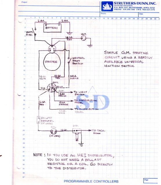
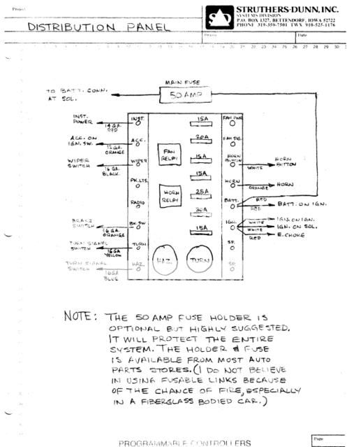
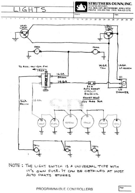
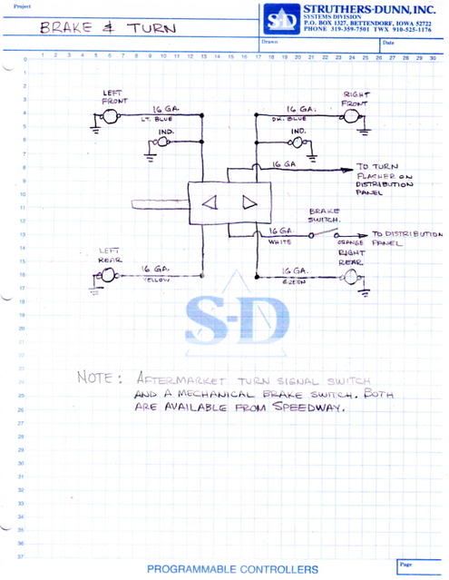
KaolaT, being the great guy he is, had given me permission to post his wiring schematics. He had made a few revisions to the ones originally sent to me, but these are the final drafts. I can vouch for the first set and I had NEVER wired ANYTHING before! The other sets should be just as easy to follow.

wiring_10001.jpg


wiring_10002.jpg


wiring_10003.jpg


wiring_10004.jpg
 
Cool :cool: thanks Fred and KoalaT :D
 
Thanks KoalaT and Fred!!! Just what I need for my attempt at wiring!!! Like you Fred, I have never wired anything either.:D:lol:

PaulR
 
PaulR said:
Thanks KoalaT and Fred!!! Just what I need for my attempt at wiring!!! Like you Fred, I have never wired anything either.:D:lol:

PaulR

Paul, the starting and charging was my main worry. If you look at the other stuff, it seems straight forward. I looked at the plans for quite a while before I started, to get an idea of how it works and why.

You should try it.
 
I like how the schematics were broken down into segments....very easy to follow. Most other schematics show everything in one diagram which can be a headache to look at.

Thanks for those.
 
Re: KaolaT's wiring schematic minor correction

Hi Bucketeers, and Tfeverfred.
Just a respectful minor correction to KaolaT's excellent schematic of the alternator/starter circuit.

If you are using a ballast resistor to limit coil current, when the starter solenoid is energised the "R" terminal wire should bypass the ballast resistor and feed full current into the coil to give extra energy for starting. When she fires up the solenoid is de energised and the coil is then fed via the ballast resistor from the ign. switch as drawn.
 
Very well done. When I wired my car using Kaola's schematic, My car kept running when I turned it to the off position. Now, Speedway has a little piece of wire in it to solve this, but I got the same diode at Radio Shack. $2.99 for 4. If this is what you are refering to, I'll search my build for the Radio part #. Heck, I got 3 left over, I'll mail 'em to anyone that may need one. The Speedway price was about $15.00 for a hunk of wire and a diode. I ain't rich, but I have 42cents for a stamp.:lol:

And by the way, we're all here to learn and love these cars. When you spot something or have a tip, drop it in. We're brothers, man.;)
 
Tfeverfred, the schematic as drawn wouldn't run on as you describe unless the "R" terminal on the solenoid is energised all the time. I just connect the ballast resistor to the solenoid terminal with the switch wire and thats it. With the engine running there should never be voltage on either solenoid terminal in any event.
Schematic as drawn won't need a backfeed diode to work. However, if you open the battery isolator with the engine running she'll keep on running because the alternator will supply voltage. If you use a 2 pole battery isolator you can also break the alternator/battery wire, but you need to run the alternator wire back to the switch instead of terminating it on the starter stud. I still like to do it this way because then the battery isolator becomes a true electrical master isolator. Just be careful because some older alternators don't like being open circuited when they running - the GM ones we get here are fine.
OK on the advice thing, as a youngster I served my time as an Auto Electrician so I know there is usually more than one way to do most auto electrics, so I be careful with advice. Yep, we brothers.
 

     Ron Pope Motorsports                Advertise with Us!     
Back
Top