Ron Pope Motorsports                California Custom Roadsters               

Keepers build

Today I finished making the headlight stands. I was going to buy some, but I couldn't find any I liked, so I made my own.

I used:

3/8 plate for the top and bottom, 1 inch .188 wall tube for the legs and 1.5 inch .120 wall for the light mount.

I am a couple steps into it when I took these pics as I tend to forget to take pics once I am working.

It took me longer setting up my little jig then it did to make the mounts! This is to make sure they both match.

27%20dec%202010%20003.JPG_595.jpg

27%20dec%202010%20004.JPG_595.jpg


I still have some final welding and clean up to do, but they turned out pretty well.

27%20dec%202010%20002.JPG_595.jpg


27%20dec%202010%20005.JPG_595.jpg


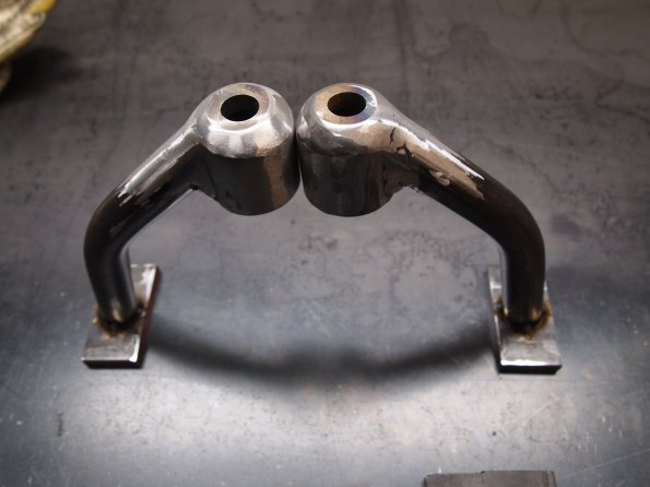
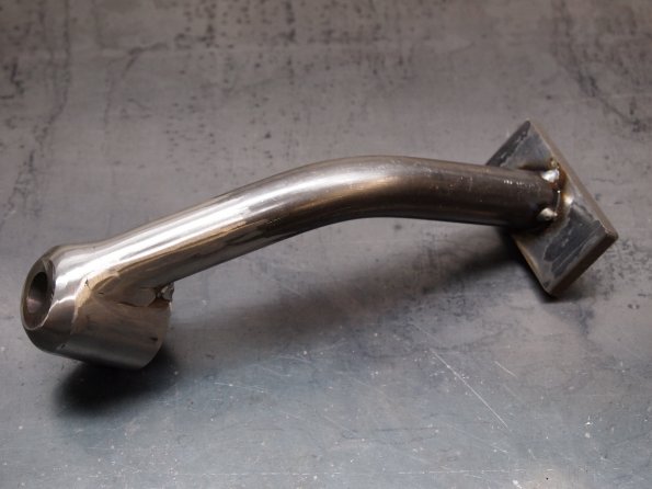
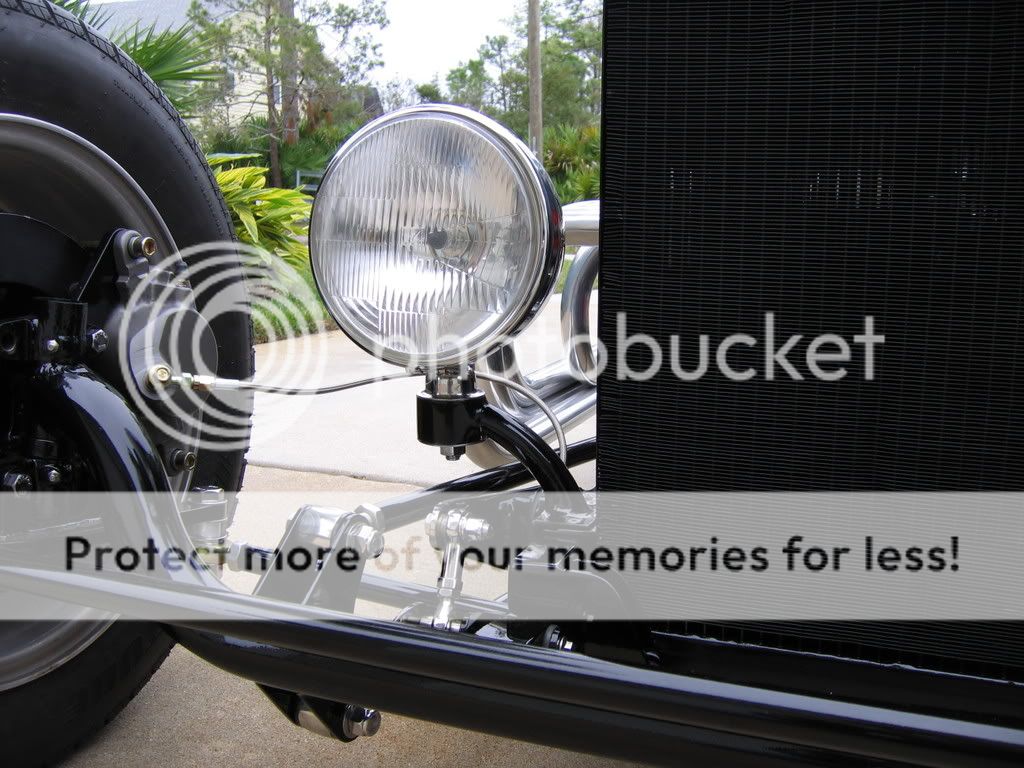
As you can see the tops are rounded, the inside has a rounded hole as well, this allows me to use the original rounded washers for adjustments, I have a ton of adjustment built into these lamps.
27%20dec%202010%20006.JPG_595.jpg


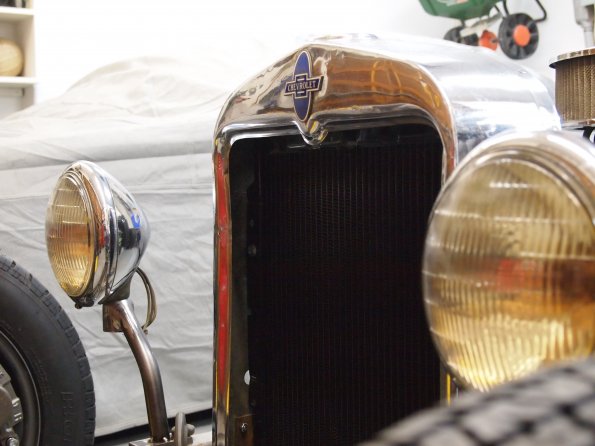
Some of you may remember my tape, well it was still there and I hit it pretty much bang on where I wanted them.

27%20dec%202010%20009.JPG_595.jpg

27%20dec%202010%20008.JPG_595.jpg


Had to check to make sure the tires were not going to hit, I knew they would not, but checked anyway!

27%20dec%202010%20015.JPG_595.jpg


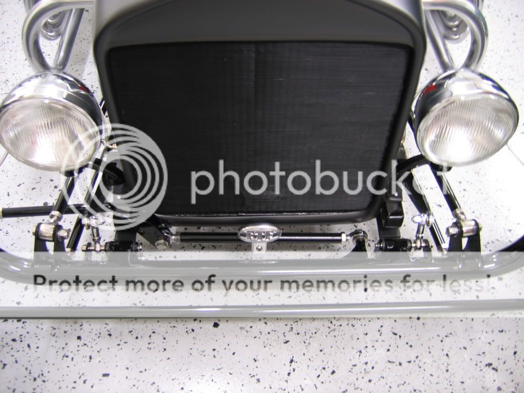
The full front shot is a little fish eyed, I was not about to open the garage door and let out all the heat!!

27%20dec%202010%20010.JPG_595.jpg


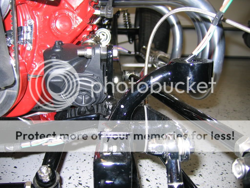
The just because shot...

27%20dec%202010%20014.JPG_595.jpg


One more step down.
 
Nice lookin mounts, the one thing I might suggest is to add a third bolt to either the inside or outside of the base. Two bolts are offen not enough to eliminate vibrations that will loosen bolts.

Ron
 
I made mine somewhat the same but used a piece of angle to mount to the frame so that there are four bolts, like Ron suggest,rather than just two. I also ran the wiring inside the mount. Here are a couple of pictures that show it during construction and at completion.

IMG_0664.jpg


IMG_0671_2.jpg


IMG_0836.jpg


If you'll notice, the bolt on mount is hidden on the top by the mounting flange of the grill shell.

Jim
 
I thought about using angle instead, but then the more I looked at them, the more I wanted them in the middle of the frame. I still have the ability to run the wires through the mounts, but my headlights have the wires coming out of the back of the bucket. I will probably run a short piece of flex conduit out of the back of the bucket, then through the legs of the mounts.

I could always drill a third hole in the center of the mount and thread it up from the bottom. If I do bolt them on, I would most likely sleeve the bolt holes through the frame.

As for shocks. I haven't decided yet! I was looking at front after I mounted the lights and have a couple ideas, I will have to get my hands on the shocks before I make a final determination.
 
Headlight stands look like a nice piece of work. Either way, I'd be proud to have them on my T
 
Well I was planning on doing the brakes next, but after reading some tips on here to do the steering first, I decided to begin that first.

Last week I went and picked up an early 70's Ford tilt column, of course before I took any pics I had torn it apart. It was originally a column shift column, but I have a cable floor shifter so all those parts will not be needed.

Here is the torn down pics:
15%20Jan%202010%20014.JPG_595.jpg


15%20Jan%202010%20015.JPG_595.jpg


Since the column shift was a tube inside a tube, I can reassemble the column without any of the shifter and still have tilt and turn signals. I am debating the use of the ignition switch as this one uses a rod to actuate a switch bolted further down the column. We will see how it goes.

Next up I put the pieces I will be using together:
15%20Jan%202010%20016.JPG_595.jpg


Then came the column placement, I used a variety of clamps to play with placement, this is not the steering wheel I will be using so things may move a touch once I find the wheel I will stick with.

15%20Jan%202010%20018.JPG_595.jpg

15%20Jan%202010%20019.JPG_595.jpg


Once I got it pretty close I but the outer tube to length and bolted it on for a test fit. This will not be the final outer tube I will make something that will cover the tube and tilt mechanism at a later date.

15%20Jan%202010%20020.JPG_595.jpg

15%20Jan%202010%20021.JPG_595.jpg


At first I thought it looked like it was sitting to far out from the dash, but after looking through 100's of pics, it seems about normal.

At least it should make things easier to get in and out.
 
Keeper,
Thats some very creative clamping, A clamp for the clamp that is holding the clamp doing the clamping, Gotta love it......ruggs
 
Keeper,
Thats some very creative clamping, A clamp for the clamp that is holding the clamp doing the clamping, Gotta love it......ruggs

lol..thats the clean edition. I had 4 going at once while I was fighting with positioning. Even called the wife out to sit in the car and see how it felt. I did this knowing that as soon as she drives it, I will be building another..lol
 
I made mine somewhat the same but used a piece of angle to mount to the frame so that there are four bolts, like Ron suggest,rather than just two. I also ran the wiring inside the mount. Here are a couple of pictures that show it during construction and at completion.

IMG_0664.jpg


IMG_0671_2.jpg


IMG_0836.jpg


If you'll notice, the bolt on mount is hidden on the top by the mounting flange of the grill shell.

Jim

In Calif, I could not get away with the headlights that low... Mine are 24 or 25 inches to center... :)
 
Its been a couple weeks since I have done anything. I was putting off the brake setup hoping to find one at the first swap meet of the year. Turns out the first swap meet was more of a flea market!

So I started planning my brake setup, I studied pics of different setups that are on the market and decided on a setup that I could make with myself.

I went with a through the floor setup with a mostly straight pedal, as that is the easiest for me to create. Next I went out to my truck and measured my pedal height from the floor and decided on about 7 inches off the floor. Then I drew up a plan to give me about 6.5 to 1.

(Sorry for the dark pic)
5%20Feb%202011%20002.JPG_595.jpg


I then gathered what I would need for the big pieces.

5%20Feb%202011%20001.JPG_595.jpg


I am using 5x5 1/4 wall square stock for the master cylinder mount. 1/2 cold rolled steel for the pedal and 1 inch 3/16 wall DOM for the pivot.

First up I measured the highest I could mount the master cylinder and leave me 1/2 clearance under the floor. Came up with a center line of 4 inches from the top of the frame. So I marked it out and drilled some holes.

5%20Feb%202011%20012.JPG_595.jpg


Then mounted the MC to make sure it would fit.

5%20Feb%202011%20013.JPG_595.jpg


Next up was the pedal, I was really dreading this task as I was not looking forward to cutting it out with either a grinder, or my bandsaw. I marked out my design.

5%20Feb%202011%20014.JPG_595.jpg


I then drilled out the holes:

5%20Feb%202011%20016.JPG_595.jpg

This will give you an idea for my pivot.
5%20Feb%202011%20015.JPG_595.jpg


Then came the hard part cutting out the pedal. On a whim I thought I would try a replacement blade I was given for a blade that snapped. Its a 6 TPI bi-metal blade. I was shocked at how easily it cut the 1/2 steel. After about 20 mins I ended up with this:

5%20Feb%202011%20017.JPG_595.jpg


After some edge cleanup with the belt sander, the final pedal:

5%20Feb%202011%20018.JPG_595.jpg


I had to stop there for now as I thought I had more of the 1 inch DOM, turns out I used it all on my headlight stands!! Have to pick some more up on Monday.
 
So today I continued on with the brakes:

I had already made the plunger rod and new clevis pin before I started taking pics, not that it was really interesting cutting threaded rod!

So here are all the parts to my system. I am up in the air on the return spring but I figured I would plan for it now.

12%20Feb%202011%20002.JPG_595.jpg


First thing was to make a clearance slot for the pedal:
12%20Feb%202011%20004.JPG_595.jpg


Once that was done I mocked it up to make sure everything worked without interference.

12%20Feb%202011%20011.JPG_595.jpg

12%20Feb%202011%20010.JPG_595.jpg


Again not sure on a spring:
12%20Feb%202011%20006.JPG_595.jpg


Once I was satisfied that nothing would bind, I welded up the pedal:
12%20Feb%202011%20013.JPG_595.jpg

12%20Feb%202011%20012.JPG_595.jpg


Then I cut the base down to size, it stands 6 inches tall now.
12%20Feb%202011%20014.JPG_595.jpg


Then it was time to fit it to the frame and work on final placement, I ran into a small issue, the shifter arm of the transmission hit the base of the mount, just glad I caught it now!!
12%20Feb%202011%20016.JPG_595.jpg


Some time with a hole saw and grinder and its all sorted out:

12%20Feb%202011%20020.JPG_595.jpg


This is where I stopped for the day:

12%20Feb%202011%20021.JPG_595.jpg


Tomorrow I will fit it to the frame with the body installed to adjust for the final fitting. The plan is to bolt it through the frame in 3 spots. The arm pivot will run through the frame and the entire unit and be held in place with cotter pins.

After looking at the post, not a lot to show for about 8 hours in the shop!
 
Nice job, Keeper. The welds look clean and nice. I always like seeing the weld. It tells you something about the build. Thanks for the photos and the update. All you guys in the cold weather country, hope you have heated garages. Ohhh! That snap-on tool feels cold!
 
Nice job, Keeper. The welds look clean and nice. I always like seeing the weld. It tells you something about the build. Thanks for the photos and the update. All you guys in the cold weather country, hope you have heated garages. Ohhh! That snap-on tool feels cold!
Snap-On? Don't they come with heated handles?
 
Nice job, Keeper. The welds look clean and nice. I always like seeing the weld. It tells you something about the build. Thanks for the photos and the update. All you guys in the cold weather country, hope you have heated garages. Ohhh! That snap-on tool feels cold!

Absolutely heated, best addition I have made to the garage:

24feb%20005.jpg_595.jpg


Dayton G73 5kw heater.

(I don't own any snap-on tools!)
 
I just have in floor heat in my garage.It is the best heat to have.
 
8 Hours later and your looking at a nice piece of work. Time does fly when working metal. And to top it all the only bit on show will be the pedal.

Gerry
 

     Ron Pope Motorsports                Advertise with Us!     
Back
Top