

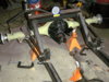
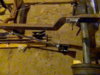
I started to lay out the 4 after contacting speedway to tell them that the angle was too much on the bar ends, but they said it was 7 degrees. I thought they should be straight any way was why i contacted them. So I decided to put one together and see what I had. this photo says it all. Any ideas? are these front bars maybe as I suspected they might be.


.jpg")


