Mr T Bucket
Member
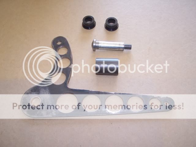
I have several pics saved of this type of setup, and am thinking this is the basic route I'm wanting to go for my front shocks. What I'm not sure about is the pivot area where it is attached to the frame. If you were going to build something similar to this, what would you use for that pivot joint? Meaning, what kind of bearing, or bushing, if any would you use? Would you use something like a half inch shanked bolt that would just rotate inside a well-lubed .505" (or similar sized) piece of round tube steel? Isn't that how most of the under floor T bucket brake pedal setups are done? My mount would most likely be welded on the top or bottom of my frame, and not through the side. I had thought about integrating a heim at that spot and another where the shock mounts just like in a CAD picture that George Barnes did some time back, but I think it might clutter up the look a little. However, I am not 100% against that idea. It's just that the stuff I keep wondering about that would be somewhat compact, like an oilite bronze or plastic bushing just doesn't seem like it would live very long. Short of lucking out and finding a thin caged needle bearing, I'm not coming up with many other options.
I also noticed no plan for movement where the shock is bolted to the top of the "L", unlike the heim at the axle. Is it because the rubber bushing in the end of the shock would "give" just enough for what might be a relatively small movement? I'm not really concerned about that aspect as much as I am the pivot at the frame, but figured I'd ask.

I also noticed no plan for movement where the shock is bolted to the top of the "L", unlike the heim at the axle. Is it because the rubber bushing in the end of the shock would "give" just enough for what might be a relatively small movement? I'm not really concerned about that aspect as much as I am the pivot at the frame, but figured I'd ask.