Ron Pope Motorsports                California Custom Roadsters               

Jag rear radius rod mounting point question

Keeper

Active Member
Okay here is the question of the day:

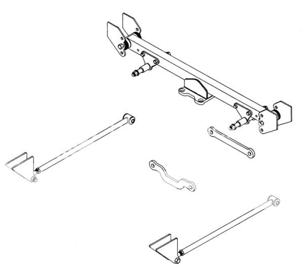
Can the transmission mount in the CCR plans be used as a mounting point for a jag rear radius rod?

I am working on making the radius rods for my jag rear, for them to mount with the correct geometry (or damn close to it) I would need to mount them to the lower portion of my transmission mount. Now the CCR trans mount bolts to an upper cross member with 4 5/8 bolts. Would that be strong enough to hold the rad rods? If not I can fab up some brackets for the frame, but I would really like to keep the geometry correct on the rear.

I figure it should work as those should not have a huge amount of force on them, well not enough to shear 4 5/8 bolts.
 
I'll defer to GAB on this, but as I understand it, there is not a huge load on the radius rods. They are there to supplement the main load carrier... the trunnions at the inboard mounts of the lower control arms. On the stock Jag installation, the front mounts of the radius arms are rubber donuts. That would cause me to believe they are more for stabilization than for major tension/compression loads. The donuts also compensate for the fact that, in the stock installation, the front mount points for the radius arms are not in the swing axis of the lower control arms. I would think you would be OK using the trans mount clip in the TP set-up.
 
You may have seen this before, but here is GAB's design for my radius rod mounts...

Assembly4.jpg
 
This is how it should be done, same as factory, to end all the binding that my old set up causes (CCR) You need a solid rear cross member in your frame, and another cross member that holds all the Jag components, this cross member should be mounted with rubber mounts, now build a working set of radius rods that mount as usual, same as the CCR frame mounts.. NO NEED for those short 5/8 or 3/4 rods that tie everything to the frame... Now the Jag is mounted like it is in a stock Jag, without any binding at all... This allows for some movement back and forth... the main lower Jag arms that hold the coil-overs and hub carrier , are the real radius rods, the new longer Radius rods will replace those ugly old stock flat flapper arms, these keep the rear end in place and keep the top rubber mounts from breaking... Simple as that... :)
 
This is how it should be done, same as factory, to end all the binding that my old set up causes (CCR) You need a solid rear cross member in your frame, and another cross member that holds all the Jag components, this cross member should be mounted with rubber mounts, now build a working set of radius rods that mount as usual, same as the CCR frame mounts.. NO NEED for those short 5/8 or 3/4 rods that tie everything to the frame... Now the Jag is mounted like it is in a stock Jag, without any binding at all... This allows for some movement back and forth... the main lower Jag arms that hold the coil-overs and hub carrier , are the real radius rods, the new longer Radius rods will replace those ugly old stock flat flapper arms, these keep the rear end in place and keep the top rubber mounts from breaking... Simple as that... :)

Ted.
I may have got your message wrong but... When you say NO NEED for those short 5/8 or 3/4 rods that tie everything to the frame... do you mean the 2 tie rods to the front of the diff. If so I would be a little worried about not using them. They stop the diff trying to turn against the wheels. Especially when you do a quick get away. If they are not there the only thing holding the diff in is the 4 bolts on the diff pad. I know of one person who did nt bother with these short tie rods and he left the rear end in the middle of the road when doing a hot take off. Also we have found that if they are mounted at 45 degrees off verticle and 45 degrees off horizontal (if you see what I mean) they tend to bend. They need to be around 60 degrees from the chassis down to the diff.
diff from front.JPG
As for the radius rods from the middle of the chassis to the end of the lower control arms. I am NOT running any at all, but my control arms and diff 'carrier' are fabricated for max strength.
Apologies if I have got what you said wrong
G
 
First, let's agree on some terminology...

CADlabels.jpg


The parts in the next diagram that I will be talking about are the "wishbone" (what I call the "lower control arm"), part number 3, which I call the "trunnion," and part number 1, which I call the pivot shaft.

Jagparts.jpg


I am by no means an expert in Jag rear-ends and chassis set-up, but I have done a lot of research and have assembled a grand total of one Jag rear-ended chassis (with considerable assistance from GAB). Here is my opinion...

The pinion struts are essential to stabilizing the differential in the chassis. As we all know, under acceleration the pinion snout wants to rotate upward with considerable torque (commonly referred to as "axle wrap," that's why we had to use traction bars on leaf-sprung rear-ends in the olden days). If the differential is held in place by only the four bolts through the diff mounting plate, a considerable bending moment is put on the mounting plate attachment points, possibly breaking welds and bending or breaking-off the mount. The pinion struts transfer that rotational force straight to the frame, stabilizing the pinion snout and relieving the bending force on the mounting plate. Ted's design using a second crossmember to help carry the load of the diff mount certainly spreads the load better than the design shown above, by I would still want to use pinion struts.

On the forward mounting point for the radius rods, while mounting the diff in rubber will allow for some "give," I believe there will still be some binding in the up and down travel of the outboard end of the lower control arm if the forward radius rod mounting point is not on the same axis as the pivot shaft. I'm going to do a CAD drawing to illustrate my point... I'll be back in a little while.
 
I think that this is what Ted is talking about. This is how I used to make my Jag rear mounting kits. It is basically the same as the stock Jag mounting theory. The crossmember is rubber bushed and allows a small amount of movement about the bushings but that movement is controlled and restricted by the radius rods. There is no need for the links to the frame from the tie bar, the same as the factory design.

JagMountingKit-2.jpg


The trouble with this design for a t-bucket is the width of the frame at the location of the crossmember. There is not enough room too fit it all in. If you are dealing with a '32 - '34 frame, it works fine. When mounting the third member housing solidly, the links are necessary to keep from cracking the welds on the mounting plate. If you are mounting it thusly, the front radius rods attachment point need to be mounted so the their pivot point is centered on a line through the inner shaft that attaches the lower control arm. Attaching the radius rod to the side of the frame creates a conflicting arc situation and suspension binding.
 
George (and Ted), I still don't understand how "axle wrap" is dealt with in that design. I can see how the radius rods would help prevent the bottom of the diff from rolling forward, but aren't you still introducing a considerable twisting force on the diff mount?

I wish I knew how to do 3D in AutoCAD. Maybe I could illustrate my point better. Maybe now is a good time to learn 3D! Don't have much else to do, right now!
 
Also, in the stock set-up, the diff is mounted in a "cage" where both the top and bottom of the diff are bolted to the cage. In my mind, this is how the stock set-up handles the "axle wrap" issue.
 
Lee,

The rubber bushings are absorbing a lot of the twisting while the pinion is trying to climb the ring gear. It isn't applying the forces to the welds as much. If you 'll remember on the stock Jag sheet metal cage there were 4 rubber blocks that tied the unit into the body structure of the car. These allow a bit of movement in the unit assembly and the paddle arms control that movement as well as transferring driving and braking forces to the body structure.

See if this makes you any more sense. Faking a sheet metal cage with tube.:)


JagRearend-BackView-2.jpg


Incidently Lee, the drawing of the Jag mounting kit is not a 3D CAD drawing. It was done on a drawing board with pen and ink long before I got into CAD. :rolleyes:
 
Very interesting ... keep it coming.

Ron
 
Does the stock mounted Jag have any rods or anything else that holds anything?? No... Only the top rubber mounts and the bottom flapper arms which can be replaced with good looking Radius rods that mount exactly the same as the stock bottom mounts, and not in line with anything else, but straight out forward... All the connector bars (front and rear) are still needed because you have removed the cage, so everything needs to be tied back together again... The new longer outside radius rods need to be as strong as the stock flapper bars were...(you could just use a single rod, or make them look like hairpin rods with only the one stock bushing at the bottom of the Jag unit) all this keeps the wheels from moving to far forward or back when in reverse... same as a normal rear end... It really is very simple, just the same as stock only it looks better without the cage...
 
I made the mistake of not doing it right years ago, have been sorry for that all these years... Gab thought that the (bushing mounted Jag) cross member would be too wide in a T Bucket frame, if you look at the CCR plans for mounting a Jag rear, you will see that the coil-overs are mounted in closer towards the third member, because the T's weight is so much less than the stock Jag, needs that extra leverage for a good ride, and still I have always had two springs made new at half the strength of the stock coils, (plus I drill those 2 shock bodies to let all the fluid out, only need two shocks working, I like the looks of 4 coils best) and do not use any spacers under the coils, some come with spacers... this way the new cross member will be shorter so as to fit the T frame fine... Now if you are using a straight, narrower frame, mine and (CCR's) are tapered from front to rear so there is no problem with width... I will be making a cross member and radius rods like this for my new car... All the power Lee has with his blown enging, he is very lucky he has not had a failure by now... Just drive them easy and enjoy the ride... :rofl:
 
Lee,

The rubber bushings are absorbing a lot of the twisting while the pinion is trying to climb the ring gear. It isn't applying the forces to the welds as much. If you 'll remember on the stock Jag sheet metal cage there were 4 rubber blocks that tied the unit into the body structure of the car. These allow a bit of movement in the unit assembly and the paddle arms control that movement as well as transferring driving and braking forces to the body structure.

See if this makes you any more sense. Faking a sheet metal cage with tube.:rofl:


JagRearend-BackView-2.jpg


Incidently Lee, the drawing of the Jag mounting kit is not a 3D CAD drawing. It was done on a drawing board with pen and ink long before I got into CAD. :rofl:

Nothing wrong with this at all. Interesting approach with the tube hoops. Only thing i would say is that the huge number of T in the UK that run Jag IRS don not bother with any location of the rear tie bar (between the trunions.) . They just use home made or purchased tie bars between the pivot shafts from the trunnions.,but they are not connected to cross member like your hoops are.
This keeps the rear end quite tidy and free looking. The front pinion straps are all thats used.. By the way the trunnion bolts are notorious for coming loose as I have mentioned before.
For sure the original Jag was rubber mounted all round for ride comfort and noise insulation, but Im not sure I would personally worry about that in a Bucket, its all down to what you want.
 
I have always had two springs made new at half the strength of the stock coils, (plus I drill those 2 shock bodies to let all the fluid out, only need two shocks working, I like the looks of 4 coils best) and do not use any spacers under the coils, some come with spacers...

So what is the stock coil strength and what did you use in yours? I have been thinking of taking the coils to a spring shop to see if they can lighten them up, but I do not know what weight they need to be!
 
So what is the stock coil strength and what did you use in yours? I have been thinking of taking the coils to a spring shop to see if they can lighten them up, but I do not know what weight they need to be!
I just bring them (spring shop) a coil and tell them I want one the same OD but half strength, simple, as they know what they are doing with springs, I do not even remember what strength they were or are now, as long as they work, that is all I worry about... I usually try and make work what I have on hand, leverage is the answer to most everything when building a chassis... :)
 

     Ron Pope Motorsports                Advertise with Us!     
Back
Top