Admittedly, I haven't thought this through..... so, I was thinking - something I can do occasionally that doesn't require much physical output.
Do you remember the rear wish bone design on early Fords? The wish bone incorporated two mounting points at the rear axle, one fore and one aft of the axle housing and then the rubber mounted ball at the front of the torque tube. The two point solid mounting at the axle housing on either side cured any notions of twist as those 85 HP flatties lit the candles coming off the line.
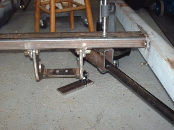
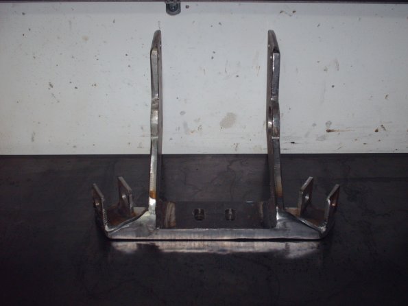
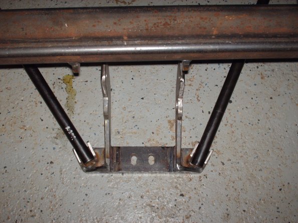
So... would it be worthy of consideration to adapt that design to the radius rods of the Jag lower control arm to resist twisting? I could envision rubber or urethane mounts rather than solid mounts at the control arm. There is a boss on the aft side of that arm that would have to be drilled and tapped for such a mount and of course the radius rods would have a connection between the two mounts sweeping under the control arm tube.


")