Ron Pope Motorsports                California Custom Roadsters               

Rear axle radius rod questions

Zandoz

Supporting Member
Supporting Member
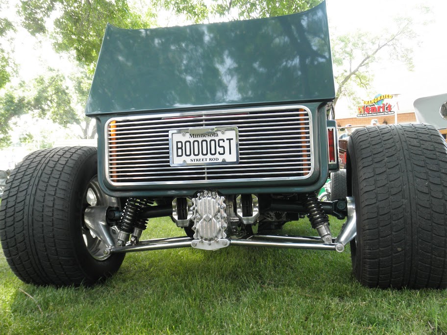
With the frame being as low as I hope (6" off the ground), the radius rods are going to have to be located as far out and down as possible to clear the body. The radius rods I'm familiar with are the hairpin and one-straight/one-curved bar styles. Both styles have serious limitations on how low they can be mounted without running into ground clearance issues

Would there be a problem using a two straight bar configuration similar to ladder bars? My thought is that this configuration would allow the forward mounting point to be lowered, giving more body clearance without running into ground clearance problems.

Another configuration I'm wondering about would be to invert the one straight bar style radius rod, putting the straight bar on the bottom, again allowing the forward mounting point to be mounted lower. Any problems with this?

How close to the brake back plates can the radius rod brackets be located? Right now it's looking like I'm going to need them 48" or more apart, on an Explorer 8.8 axle that is 59.5" between wheel mounting surfaces.

Regardless of what style rods I use, I'm going to need some kind of an outrigger setup to get the forward mounting points out from under the body. I'm figuring abut 4.5" out from the frame. Any ideas on how to accomplish that?

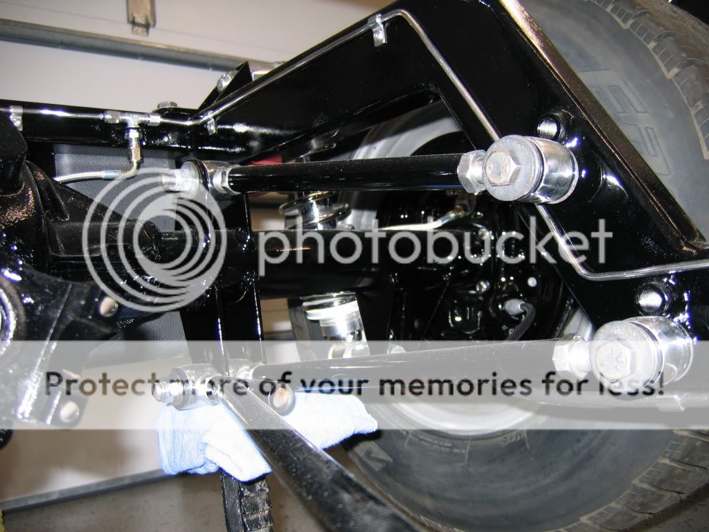
Does anyone have pics of other low frame radius rod set ups?
 
Have you tried thinking inside the frame. I have posted a picture of my adjustable four link set up that may give you some ideas. My car sits quite low and rides and handles very well.

IMG_0675_2.jpg


Jim
 
Have you tried thinking inside the frame. I have posted a picture of my adjustable four link set up that may give you some ideas. My car sits quite low and rides and handles very well.

IMG_0675_2.jpg


Jim

With the body set back as far as I hope, I don't think I have room for an inside the frame set up. As the plan stands now, the leading edge of the kick-up would only be around 10" forward of the axle center line...and with the axle hitting the bump-stops using 27" rods, the axle center line would only be about 7" from the leading edge of the kick-up.

I wish there was a way to display a DXF file on here...it would probably help to see the plans at this point.
 
Ladder bars on the inside of the frame rails...need to clear crossmembers and other junk. And you'd need something to keep the rear end centered, like a Watts link or a Panhard rod. But there would be some twisting of the bars as one side bounced and the other side didn't. This three dimensional thinking makes my head hurt...how about a nice IRS?
P6170010.JPG
I wish I could afford to go with an IRS set up...LOL. As is the plan includes a Panhard bar. I'd prefer a Watts link set up, but there is not enough vertical clearance without jacking the fuel tank too high
 
With the body set back as far as I hope, I don't think I have room for an inside the frame set up. As the plan stands now, the leading edge of the kick-up would only be around 10" forward of the axle center line...and with the axle hitting the bump-stops using 27" rods, the axle center line would only be about 7" from the leading edge of the kick-up.

I wish there was a way to display a DXF file on here...it would probably help to see the plans at this point.

Bill,

I assume you have some type of cad program if you have a dfx file. If so, most of them will convert it to a PDF format. If you need a very good and very free cad program google "draftsight". It is a Dassault free download and a very good one at that. I've used Autocad 2000 for years buyt went to Drafsight due to needing to open 2011 created drawings from customers. It's everything autocad is. Hope this will help you.

George
 
Here's something you don't see every day:

mumford%2520with%2520text.jpg


It's a clever variation on the Watts link, allowing flexibility in where the links connect to the rear end and the frame. It's used in sports cars, where they get all excited about roll center and such.

And you can also do the Watts thing horizontally if height is a problem.

PotvinGuy,

That is another way to attack the problem. As the article states, you can mount the watts linkage in the horizonal plane either as shown or conventionally without the extra pivot point. As these cars are usually pretty narrow on that regards I would lean toward horizonal and under the rear housing method. This would really be a pretty simple way to have your cake and eat it too. It's definately on my radar.

Just for the record, I lived in the Fort Worth area for over 30 years and had the pleasure of seeing your car several times. The last time was at the last Goodguys at the NASCAR track north of Fort Worth that I attended. . I took a number of pictures for a friend of mine as he really wanted to do a front drive blower. Unfortunately he passed away before getting to that project. Still a very unique roadster.

George
 
Bill,

I assume you have some type of cad program if you have a dfx file. If so, most of them will convert it to a PDF format. If you need a very good and very free cad program google "draftsight". It is a Dassault free download and a very good one at that. I've used Autocad 2000 for years buyt went to Drafsight due to needing to open 2011 created drawings from customers. It's everything autocad is. Hope this will help you.

George

What I have is an ancient DOS version of AutoSketch. For over 20 years I've been using it for everything from designing model railroad layouts to whole homes. At this point using it is almost as easy as breathing....LOL. Unfortunately no PDF capability though. I've tried tried a couple other free download CAD programs over the years, but I've never found one I liked enough to keep me from reverting to old habits. Right now I have nanoCAD, but I'm not liking it at all. I will check check out Draftsight.
 
Here's something you don't see every day:

mumford%2520with%2520text.jpg


It's a clever variation on the Watts link, allowing flexibility in where the links connect to the rear end and the frame. It's used in sports cars, where they get all excited about roll center and such.

And you can also do the Watts thing horizontally if height is a problem.


Iff I had the $$$ I'd go for one of the differential cover mount Watts link set up that are out there for Mustangs...but they are SERIOUSLY pricey.
 

Attachments

  • Watts Link.jpg
    Watts Link.jpg
    20.2 KB · Views: 19
My radius rods mount to the trans crossmember and work great. I don't see how your frame rails could be so low unless the transmission is way up inside the car. If you have clearance for your transmission, you should have room for radius rods.
 
My radius rods mount to the trans crossmember and work great. I don't see how your frame rails could be so low unless the transmission is way up inside the car. If you have clearance for your transmission, you should have room for radius rods.

Yes, the car is going to be that low...the bottom of the frame rails will be about 6" off the ground. The transmission being up in the car is part of the reason I'm planning on using a 27' body, and offsetting the motor and transmission slightly to the passenger side. The lowness of the frame is not the whole reason for not going with an inside the frame set up...the big part of it is the fact that this will be a short wheelbase car (around 96"), with the body set as far to the rear as possible. A 4-bar set up would end up with 7" or so upper bars, and a ladder bar set up would eat up precious under-seat areas needed to house mufflers, battery, fuel pump, ECM, and the main wiring panel. In a car this small there is no place else to put all that.
 
Iff I had the $$$ I'd go for one of the differential cover mount Watts link set up that are out there for Mustangs...but they are SERIOUSLY pricey.


Bill,

This is easier then you think. You don't need to spend a lot of money to do the same thing the Mustang guys are doing. You have a DOS version of cad (Damn you're tough) so you can lay out you're geometry. All you need to do is fabricate that back cover. If you have access to a vertical mill with a digital readout you're half way there. He is how I would do it.

If you want to just hit the bricks running then we'll use method #1.
Cut a steel plate that will cover the entire back surface of the differential case. Get some threaded bline screw transfer punches. These are available through ant good machine tool store (MSC, Travlers etc) and cost about $12.00 a set (about 6 screws of the same thread). The brand name is Heimann.
www.heimannmfgco.com
You screw two of these into opposite sides of the bolt pattern and take a hammer and tap it over each punch. Remove the plate and drill to the diameter of the factory cover bolts. Remove the two blind punches and install all of the punches you have in the set in the remaining holes. Bolt down your plate and finish transferring the remaining punch marks. Now scribe or mark out the perimeter of the plate to match your case or gasket. Now the hole in the center. Mark the inner perimeter based on your gasket. Measure and make a layout pattern for minimum clearance for your ring gear and differential carrier. That pattern is all you want to cut out. You can plasma cut, torch cut, machine or use a cut off wheel. I prefer any of the col cut methods as they induce very little warping. You do remember I ask about a mill don't you? Just to help you stay flat as possible you might want to use 3/8" steel for this part. No less then 1/4". Once you get this part done you bolt it down using all 10 or how many bolts. Go look at some of the on line pictures of the 9" Ford fabricated rear housings. Notice how they are folded from flat panels. Just work you up a flat side cone that will clear the ring gear and carrier and copy it in metal. To save you a lot of press break time you cam fab the whole thing from small rectangles. Just take your time and get the back flat panel parallel with the gasket surface. Tack weld all of the panels in place. Just weld in short sections and keep moving around. Don't get the assembly to hot as you don't want to warp the steel bolt down ring if you can help it. Walk away and do something else till it cools down a bit. Once you have it welded out you can disk sand your welds and blend it in till you're satisfied. You might have to surface the gasket side if you got it to hot. Look for an engine shop that rebuilds cylinder heads. Don't go to a racing shop. Find one that does commercial work. They usually have horizontal belt sanders that have 12" wide belts that they run big heads on. It won't take but a few minutes to bring that surface back flat. And that's all there is to it. Bolt it on and measure from each end of the housing to find the true center line and that's where you put your watts linkage bell crank. Make your fabbed flat cone out of 3/16" to 1/4" material. These things can see a lot of loads real quick. Also don't skimp of the linkage tubes. I see some really small tube diameters in these kits and I really don't like them. I think you got this thing figured out so the rest is a piece of cake I don't post much these days but I do keep posted on what you guys are up to. I wish I had more time but for now life is what it is. I've been doing this stuff since the early '70s and I've made every mistake there is to make. Maybe later I'll post some links to some of my stuff. Till then, have fun. Any questions just fire away.

George
 
If your transmission clears the ground, the radius rods will clear as well. My wheelbase is only 93" and I can run very long rear radius rods which really keep the rear wheels on the ground. Anything that's very short or very angular may make your rear end hop.
 
Bill,

This is easier then you think. You don't need to spend a lot of money to do the same thing the Mustang guys are doing. You have a DOS version of cad (Damn you're tough) so you can lay out you're geometry. All you need to do is fabricate that back cover. If you have access to a vertical mill with a digital readout you're half way there. He is how I would do it.

If you want to just hit the bricks running then we'll use method #1.
Cut a steel plate that will cover the entire back surface of the differential case. Get some threaded bline screw transfer punches. These are available through ant good machine tool store (MSC, Travlers etc) and cost about $12.00 a set (about 6 screws of the same thread). The brand name is Heimann.
www.heimannmfgco.com
You screw two of these into opposite sides of the bolt pattern and take a hammer and tap it over each punch. Remove the plate and drill to the diameter of the factory cover bolts. Remove the two blind punches and install all of the punches you have in the set in the remaining holes. Bolt down your plate and finish transferring the remaining punch marks. Now scribe or mark out the perimeter of the plate to match your case or gasket. Now the hole in the center. Mark the inner perimeter based on your gasket. Measure and make a layout pattern for minimum clearance for your ring gear and differential carrier. That pattern is all you want to cut out. You can plasma cut, torch cut, machine or use a cut off wheel. I prefer any of the col cut methods as they induce very little warping. You do remember I ask about a mill don't you? Just to help you stay flat as possible you might want to use 3/8" steel for this part. No less then 1/4". Once you get this part done you bolt it down using all 10 or how many bolts. Go look at some of the on line pictures of the 9" Ford fabricated rear housings. Notice how they are folded from flat panels. Just work you up a flat side cone that will clear the ring gear and carrier and copy it in metal. To save you a lot of press break time you cam fab the whole thing from small rectangles. Just take your time and get the back flat panel parallel with the gasket surface. Tack weld all of the panels in place. Just weld in short sections and keep moving around. Don't get the assembly to hot as you don't want to warp the steel bolt down ring if you can help it. Walk away and do something else till it cools down a bit. Once you have it welded out you can disk sand your welds and blend it in till you're satisfied. You might have to surface the gasket side if you got it to hot. Look for an engine shop that rebuilds cylinder heads. Don't go to a racing shop. Find one that does commercial work. They usually have horizontal belt sanders that have 12" wide belts that they run big heads on. It won't take but a few minutes to bring that surface back flat. And that's all there is to it. Bolt it on and measure from each end of the housing to find the true center line and that's where you put your watts linkage bell crank. Make your fabbed flat cone out of 3/16" to 1/4" material. These things can see a lot of loads real quick. Also don't skimp of the linkage tubes. I see some really small tube diameters in these kits and I really don't like them. I think you got this thing figured out so the rest is a piece of cake I don't post much these days but I do keep posted on what you guys are up to. I wish I had more time but for now life is what it is. I've been doing this stuff since the early '70s and I've made every mistake there is to make. Maybe later I'll post some links to some of my stuff. Till then, have fun. Any questions just fire away.

George

I wish I had remotely near that kind of fabricating skills. I'm coming back to this after a long time away...it's been 30+ years since I've even done a tack weld...LOL. If I ever get that far with this project I'll probably set it up with a simple Panhard rod first, then try something fancy like this. One probably bad idea I've had is to try and incorporate a frame mounted Watts pivot point into the frame structure I'll eventually be adding for a trailer hitch.
 
If your transmission clears the ground, the radius rods will clear as well. My wheelbase is only 93" and I can run very long rear radius rods which really keep the rear wheels on the ground. Anything that's very short or very angular may make your rear end hop.

The bottom of the transmission and oil pan will both be at or above the bottom of the frame. As the plan stands right now, I'll be using 27" radius rods if I can find them. With typical low-mount axle brackets, and the forward mount as low on the frame as I can go, the angle would only be around 2 degrees.
 
The bottom of the transmission and oil pan will both be at or above the bottom of the frame. As the plan stands right now, I'll be using 27" radius rods if I can find them. With typical low-mount axle brackets, and the forward mount as low on the frame as I can go, the angle would only be around 2 degrees.
We custom make radius rods to your specs, so when your ready we have what you need. Just a phone call away.
 

     Ron Pope Motorsports                Advertise with Us!     
Back
Top