First let me say as many others have, George your drawings just make me want to go out and build what ever it is you have drawn. They are just enough to allow you to "see" what is needed and make any small adjustment that may be needed to make a very attractive and uncluttered part or bracket. All of these should be achived someplace for future reference.
My pedal goes down into the floor instead of forward but like all these things you exchange one clearence problem for another.
")
I am trying to use smaller pictures.
Randall
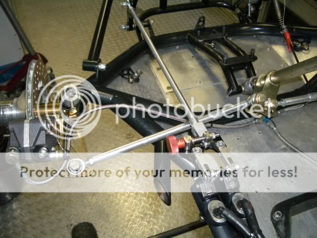
Not a good shot but my pedal
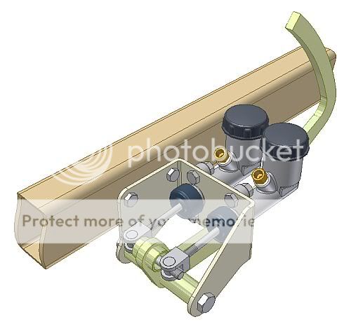
This is all the parts to make it.

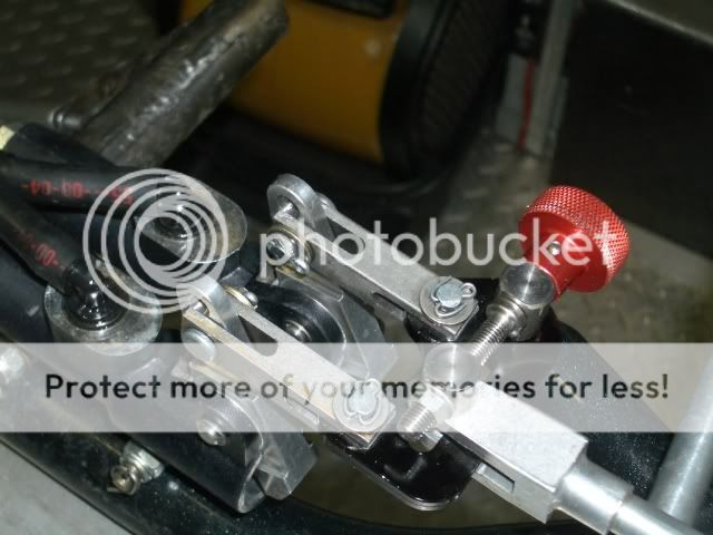
And how it looked assembled but not installed.


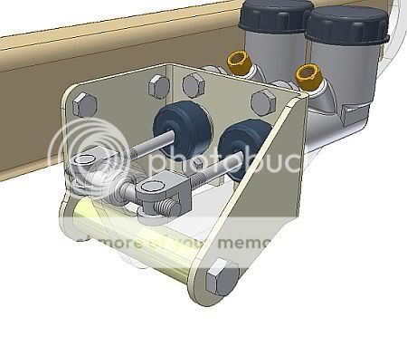

 In many race cars the adjustment shaft is connected to a cable with a twist knob close to the driver so he can adjust things (while driving if needed) for any type of stopping power desired... a little more to the front? or rear? just a small twist & wolla, it's done
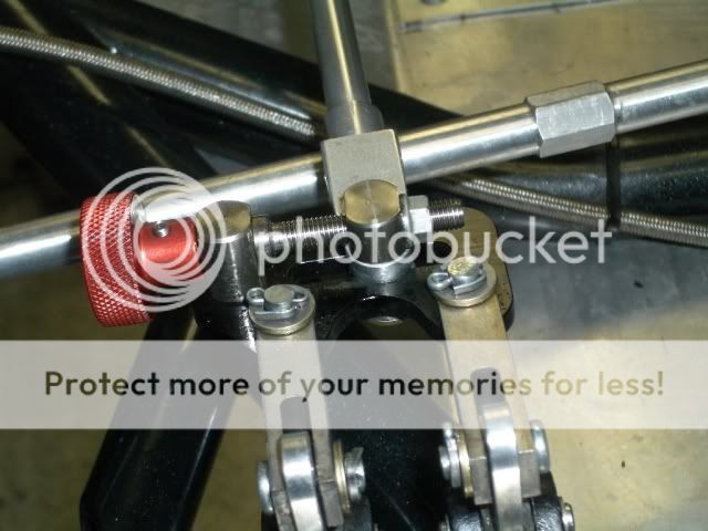

.jpg")
.jpg")
 edal-assembly-(10).jpg]


