I've been asked to post my 26T build here, hope you enjoy it as much as me.
Just started collecting parts for a new project, Hopefully my 32 will be soon finished and I'm really getting the urge for some track action again, Was going to uprate my T but it would mean some major modification which would spoil the look to be honest so decided to start afresh.
New project will be a street & strip car and as my T will have crossplys, Body will be channeled 4" over the frame but full height.
I've picked up a 26T Coupe body which will have a heavier duty version of my T chassis under it as the motor is going to be a Cadillac 500ci I picked up, I had a bit of luck as I was going to buy all the parts for the engine from MTS who are one of the Caddy experts but when I joined their forum I managed to pick up all the parts for the engine from a guy in the states as brand new parts still in the boxes 30% cheaper than new")
Engine should end up at 500+ cubic inches and has the following spec
10-1 Keith Black +60 pistons
Scat forged rods
MT20 very lairy Cam
MTS Valve train conversion
MTS Heads
Edelbrock ported intake
Edelbrock EPS 830 carb
Full balance
Cloyes heavy duty timing chain
2" Headers
Art Carr TH400 with transbake (Thanks Crusty)
B&M 2200 stall convertor
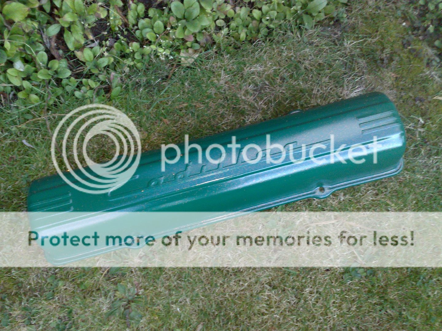
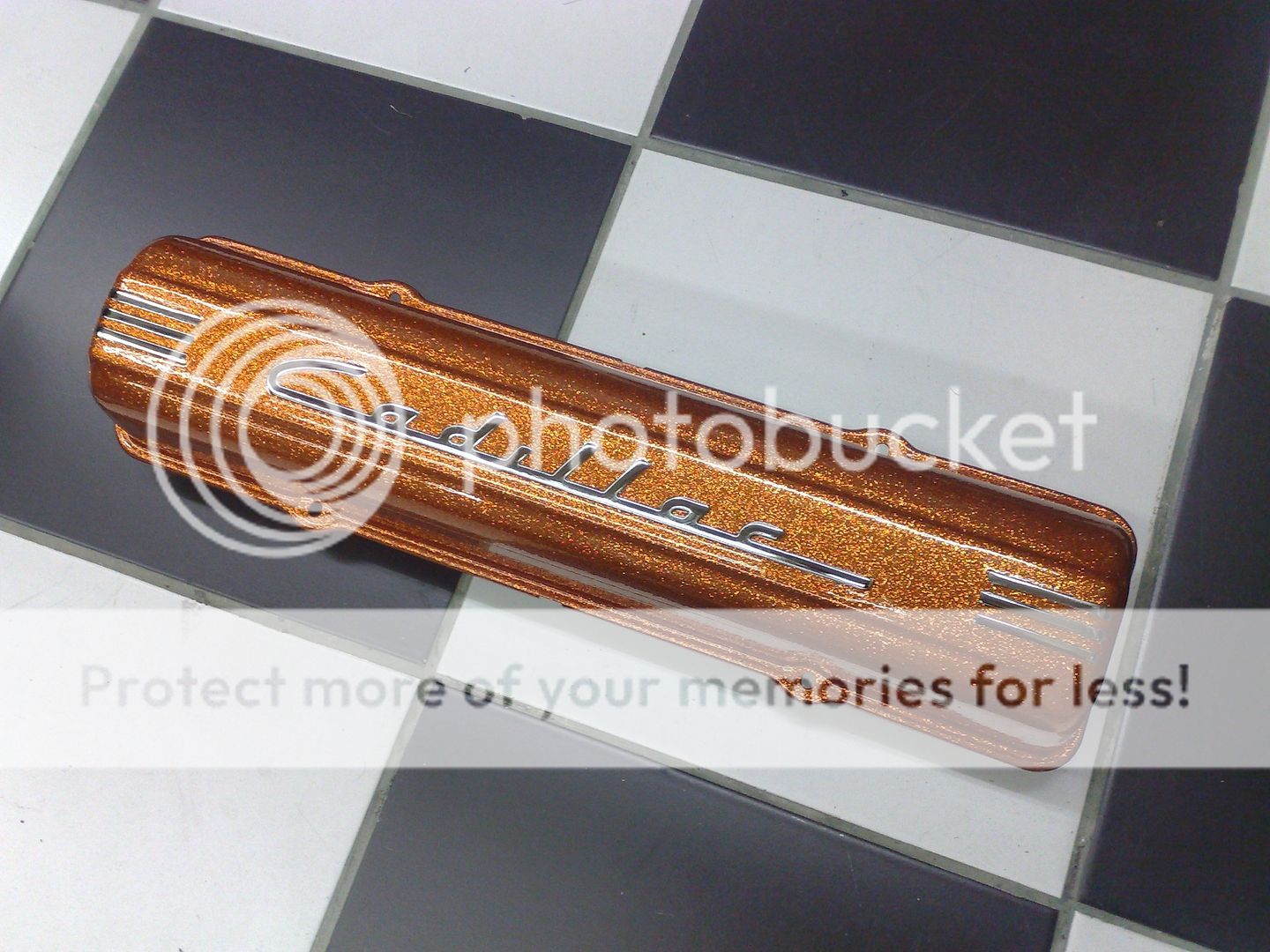
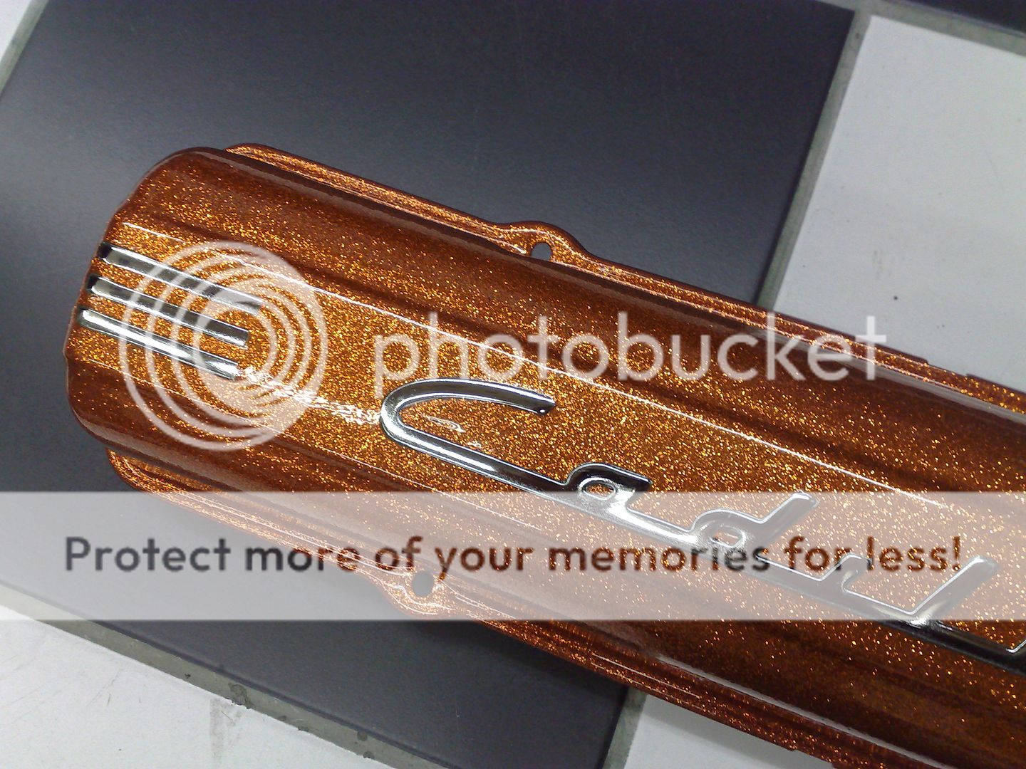
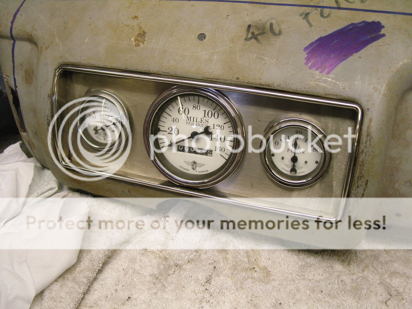
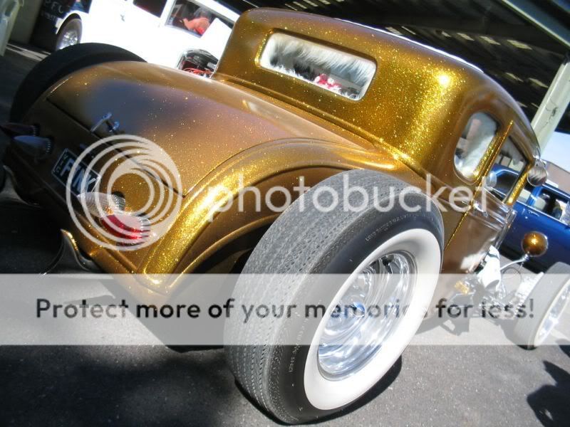
My aim is to build a 60's style T again with Radir Tri ribs, Copper metalflake paint & a White fur interior !!! Hope to run very low 11's or maybe high 10's on crossplys, Maybe more on slicks.
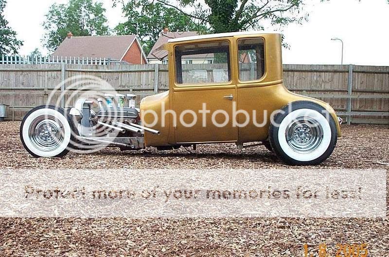
I'm aiming for this kind of look but with Copper flake and obviously a 26T body
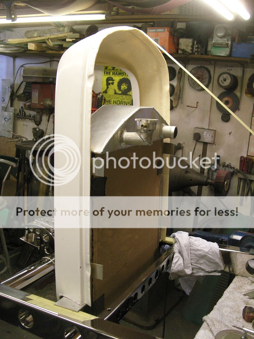
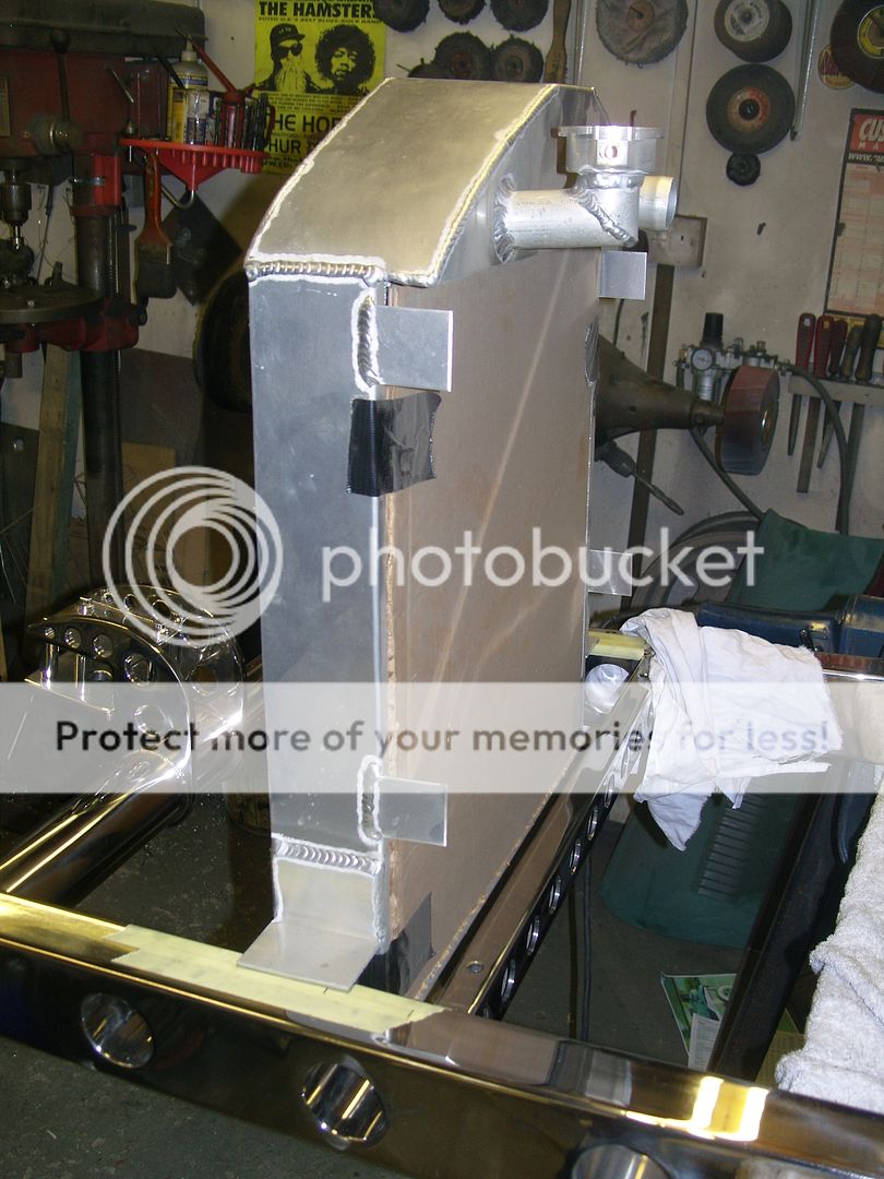
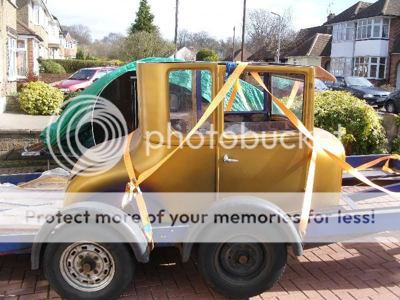
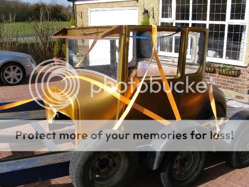
Here's a few pics of the used body i bought
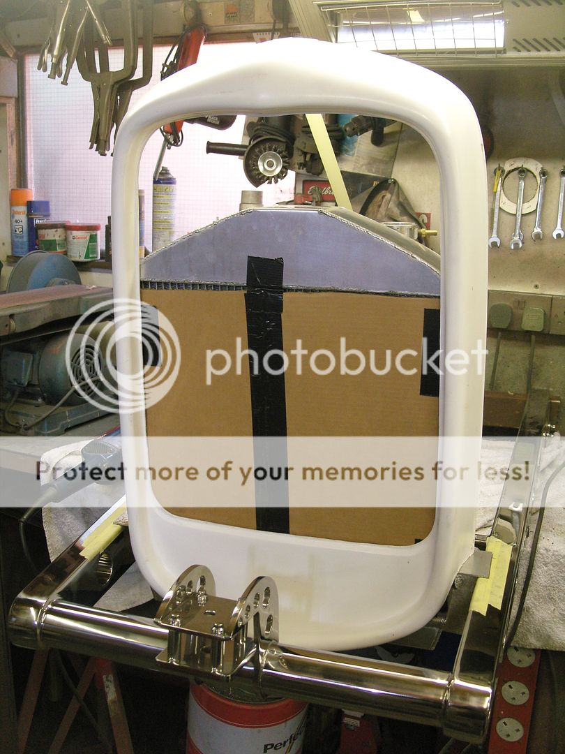
Here it is mocked up on a friends frame, This is very much how mine will look.
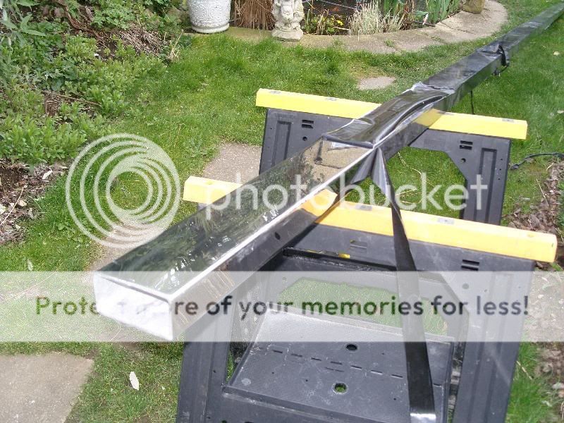
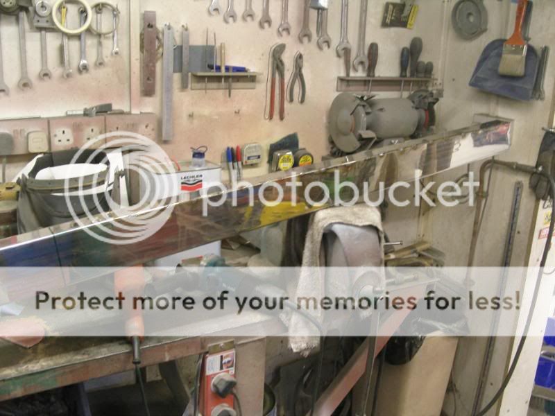
Sue has been telling me to move the 6metre length of polished 100mm x 50mm stainless box from the side of the house, wasn't quite sure where to put it so decided to cut it up to size, I got a bit carried away and ended up making the side frame rails, still save having to do it later !!!
This is what i started with.
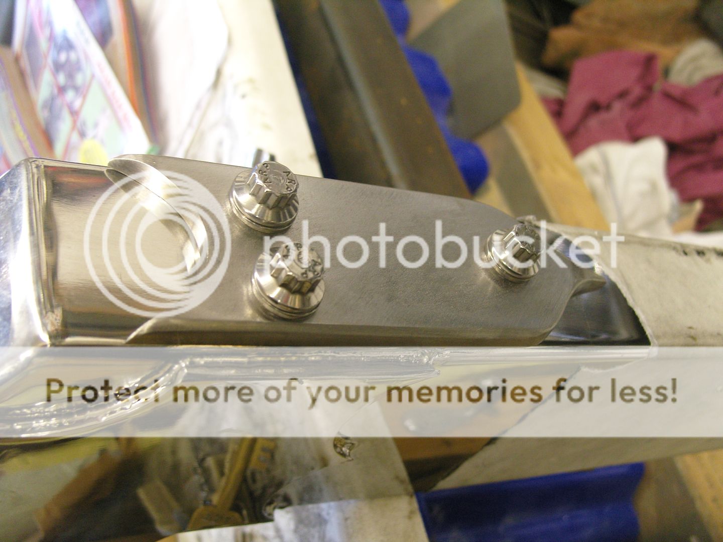
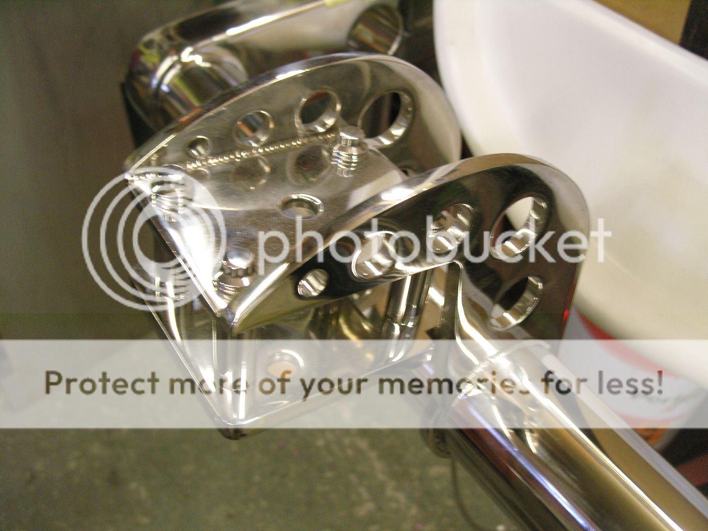
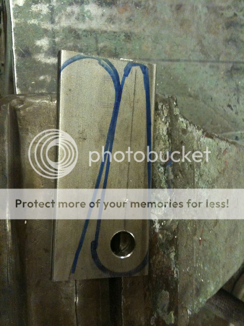
This is the front suicide mount which i drew up and had laser cut.
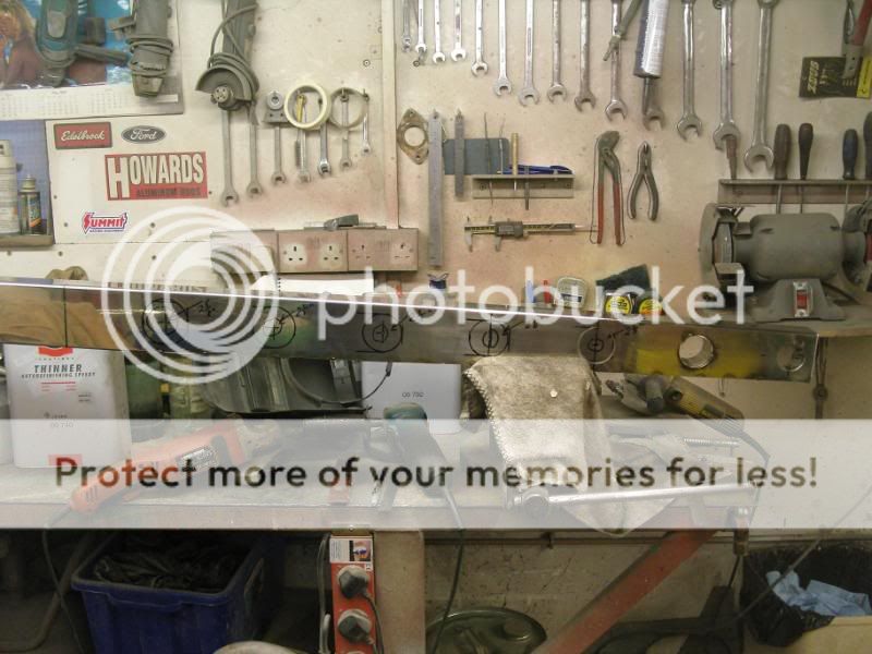
Here the side frame rails are marked out, the chassis design is the same as my 23T but i've goneup a size on the box as the Caddy motor has twice as much BHP and Torque as the 23T. The 100mm x 50mm looks very klunky on the front of a T so from the firewall forward will taper to 3". Side rails also taper in from the firewall 3 degree's
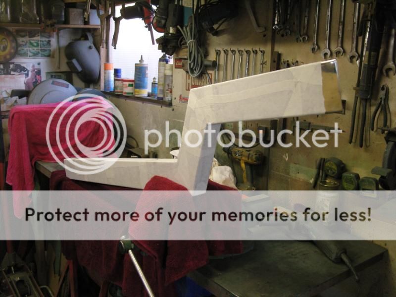
Here's the mockup in Ply
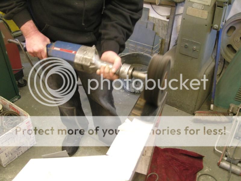
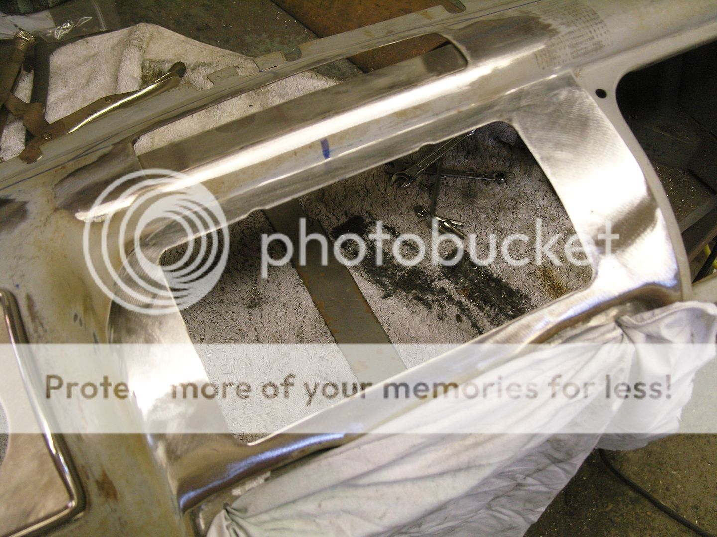
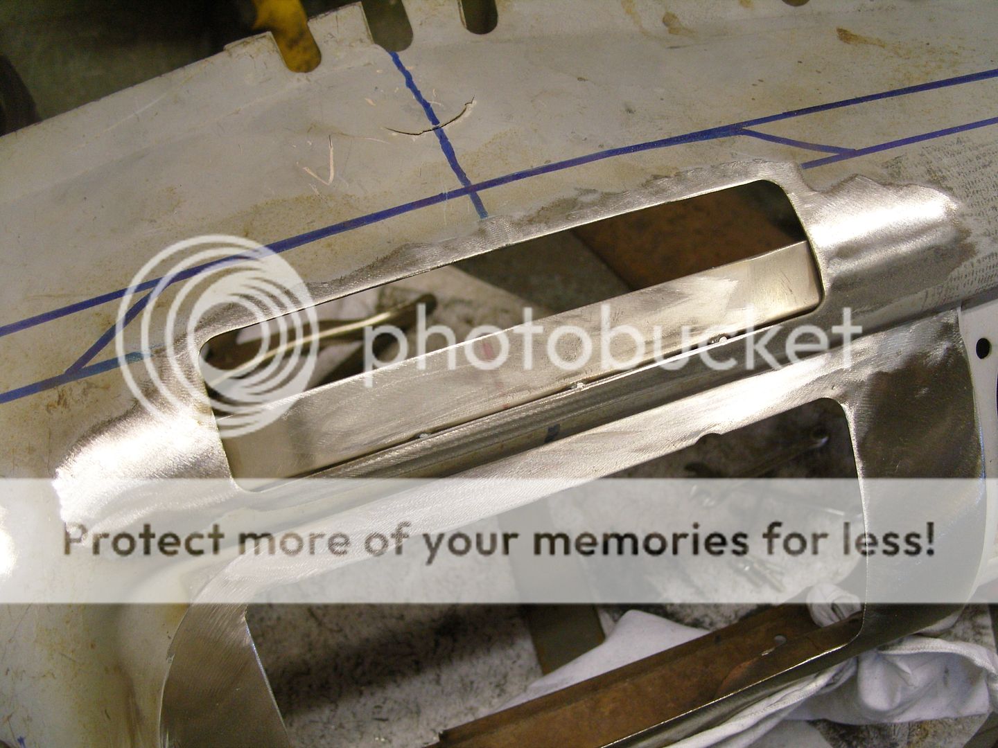
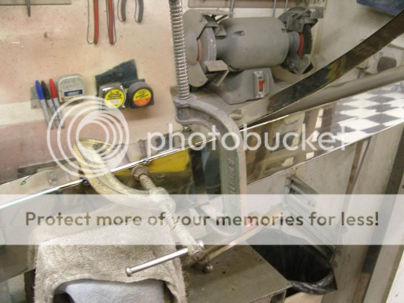
Once i had the side rails marked out it was time to get the 9" grinder out which was fitted with a 1mm stainless cutting disc and the sides were sliced. once i had finished cutting i noticed that the sides of the box had moved all over the place, this will be corrected with clamps before tack welding.
Here is the side rail being clamped back together and tack welded.
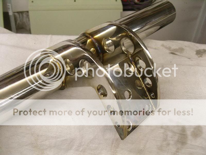
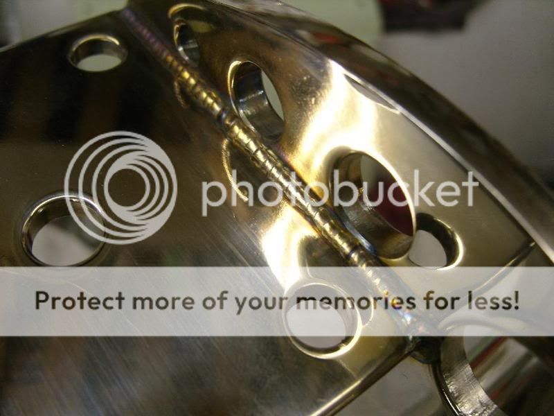
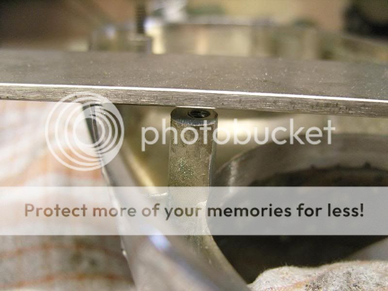
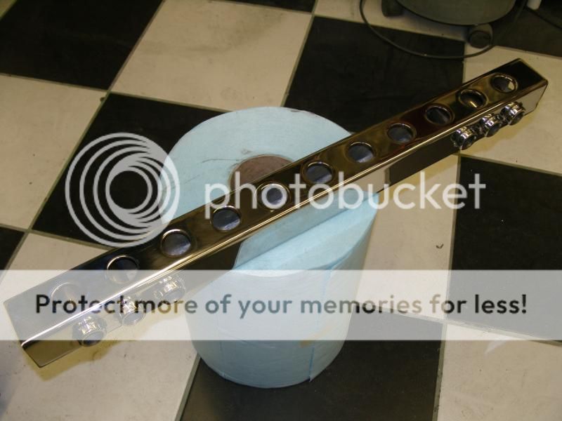
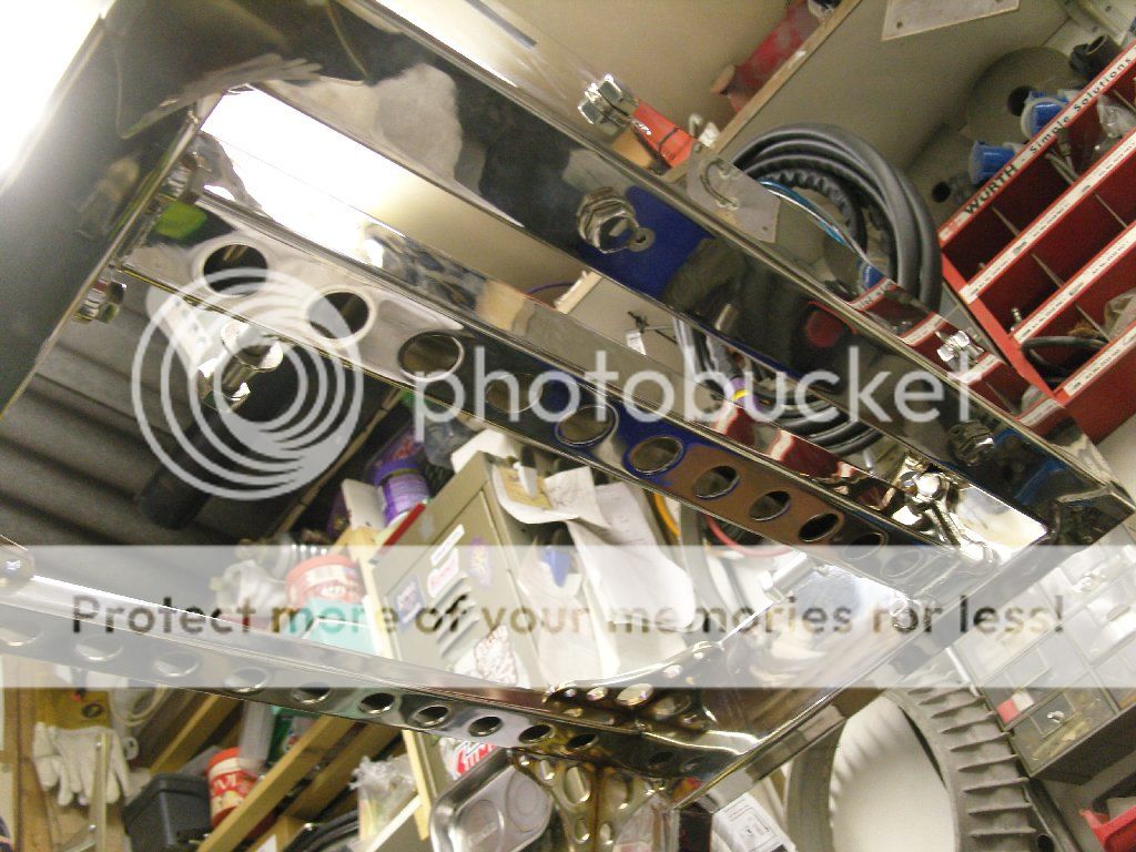
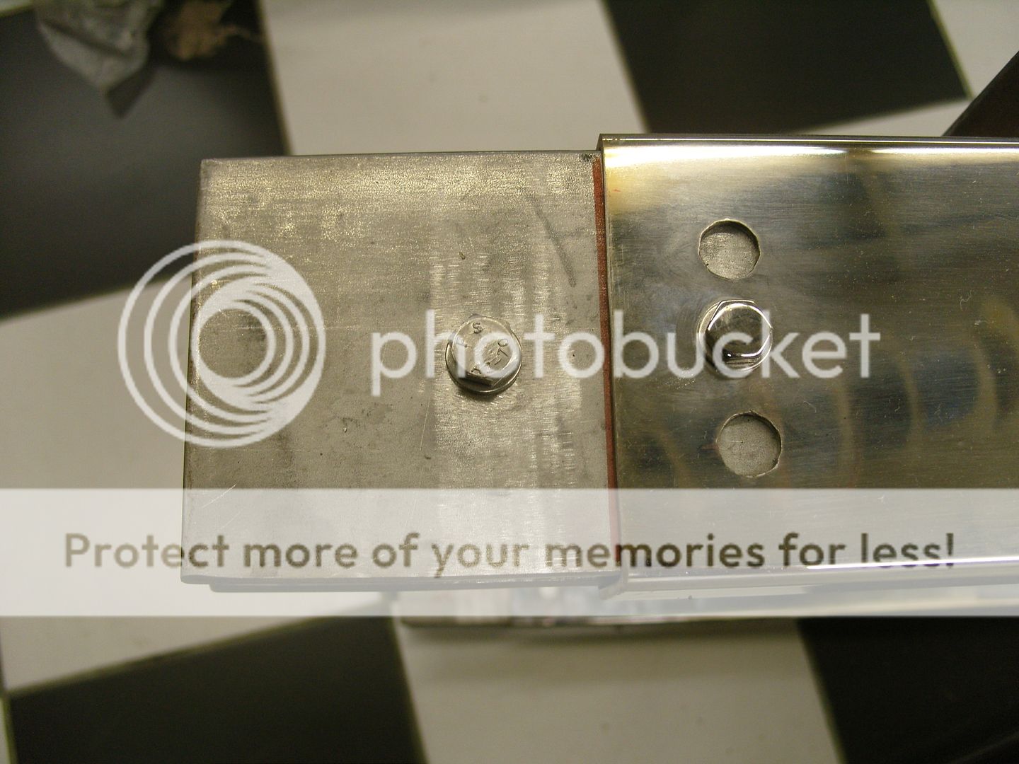
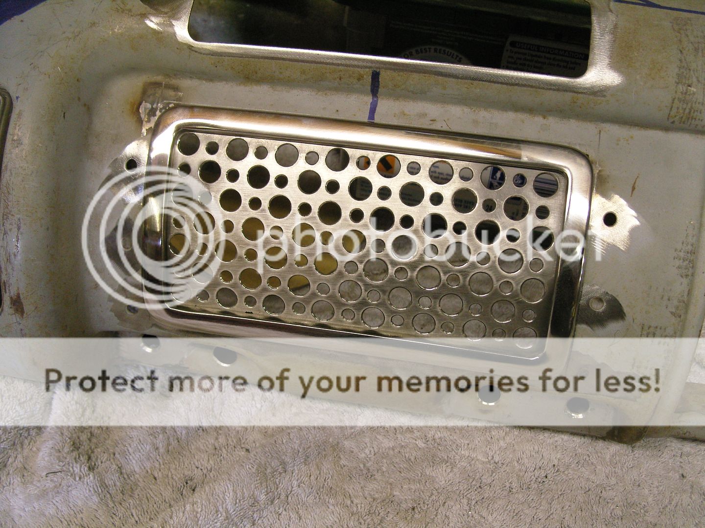
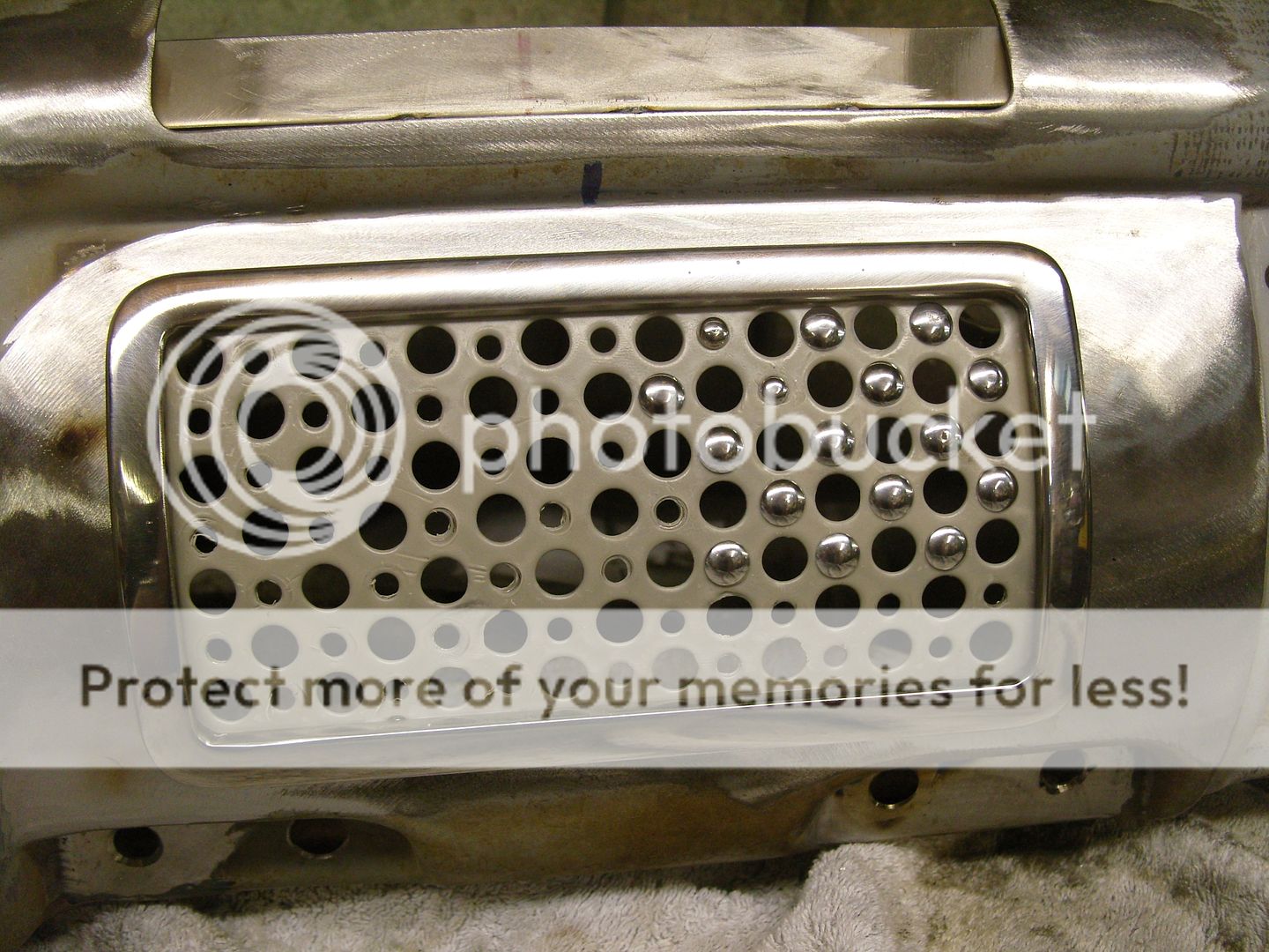
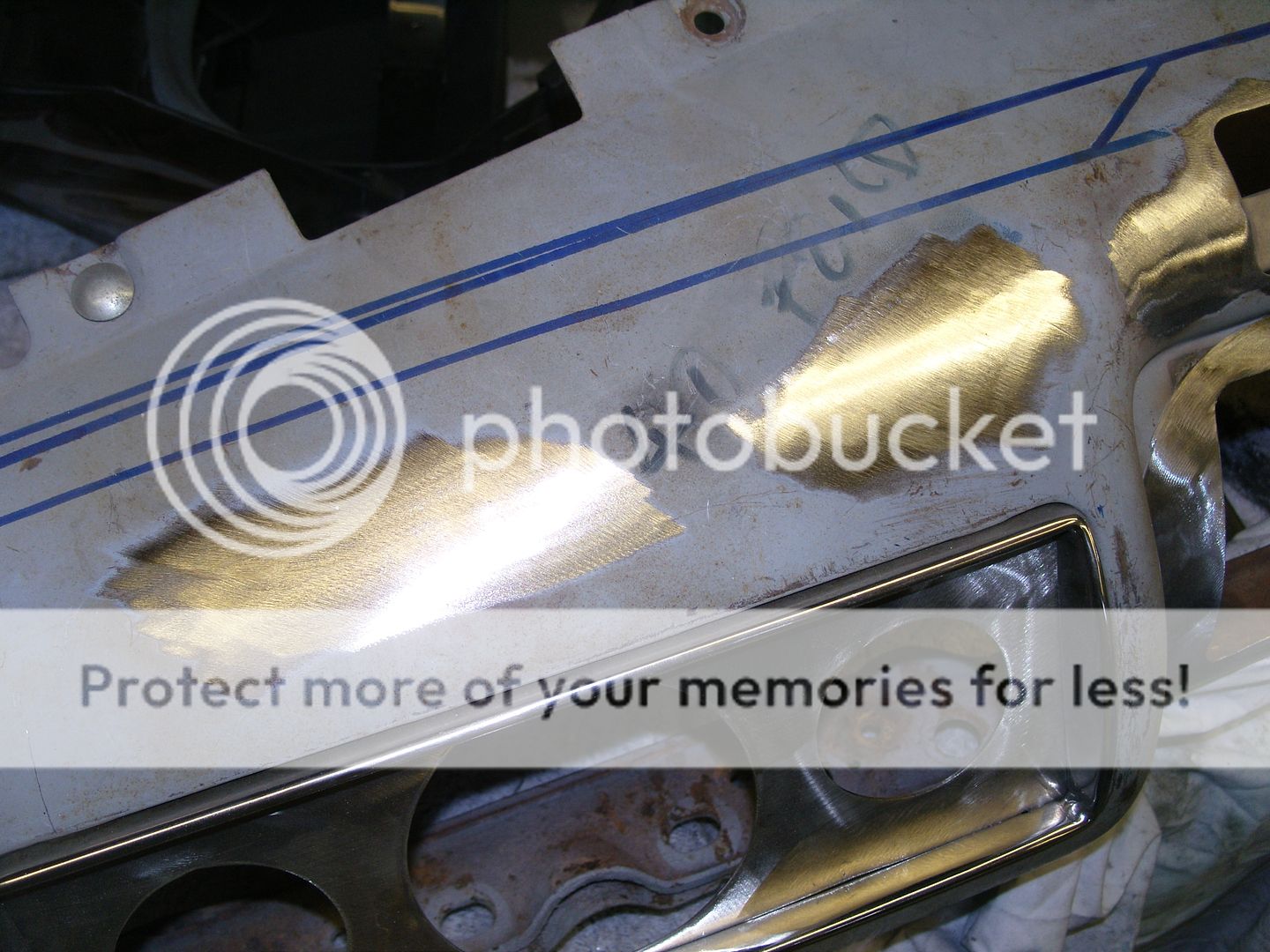
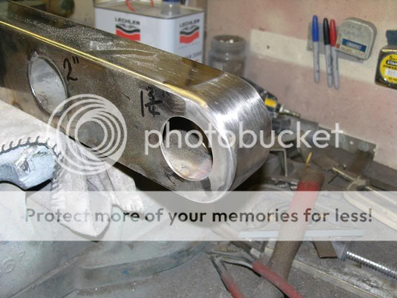
Here i'm marking out the lightning holes in the side rail, they are graduated to suit the taper and will be sleeved
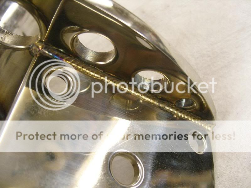
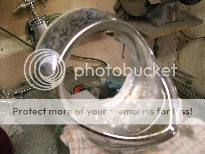
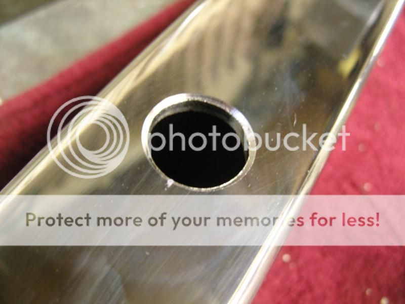
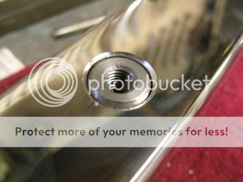
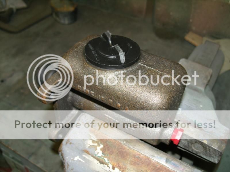
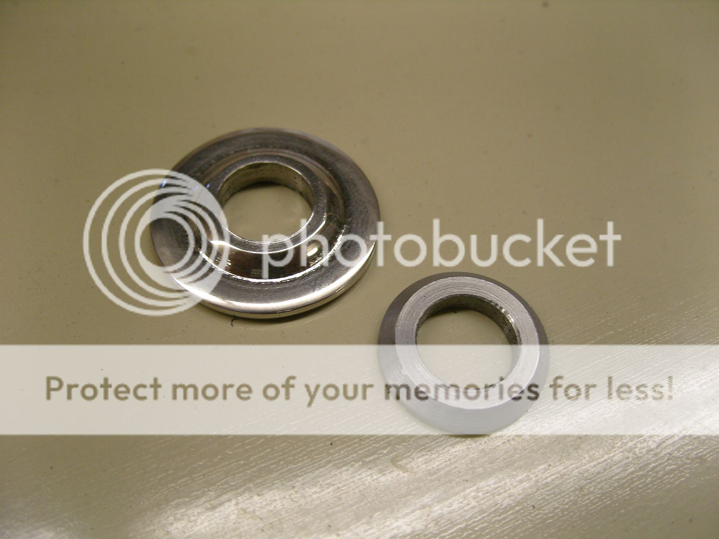
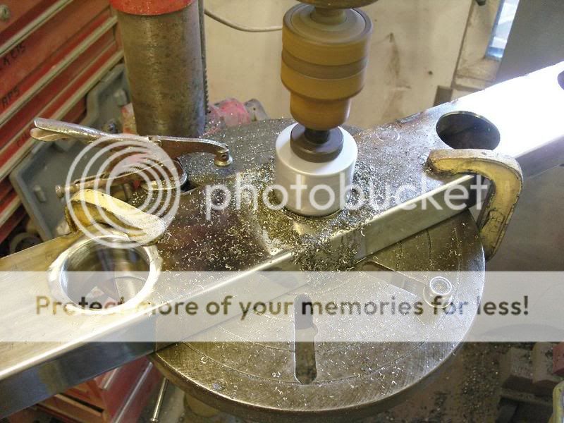
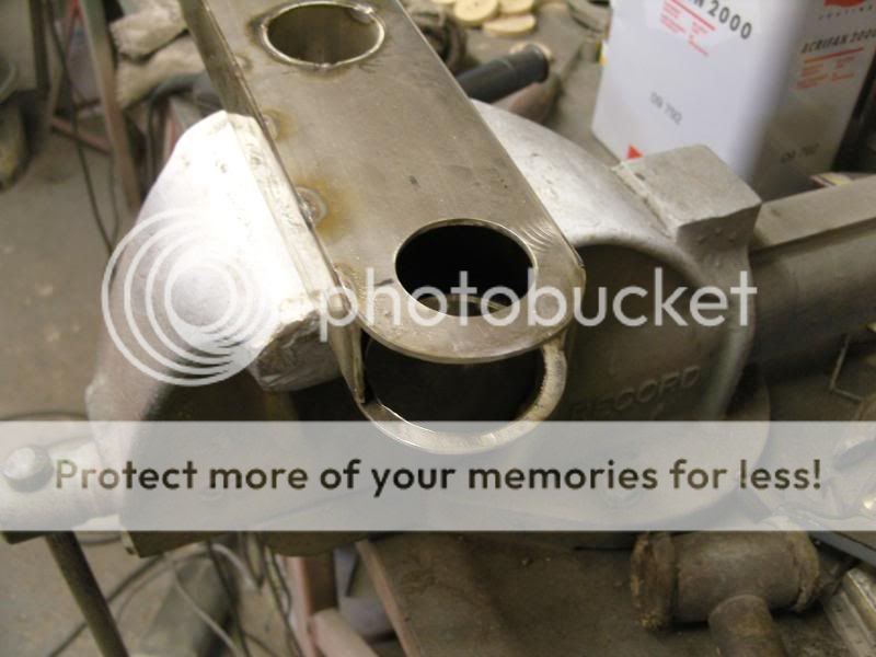
Holes were cut with a selection of good quality hole saws, they cut perfect holes out quite easily, i used 1/8" wall tubing to sleeve them but due to the holes being graduated some are not available in stock size so i will turn the odd sizes on the lathe.
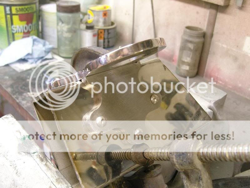
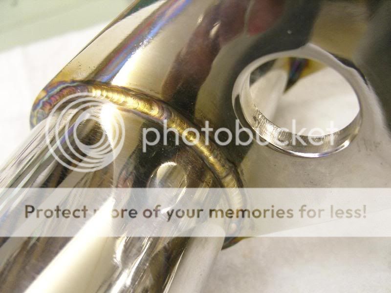
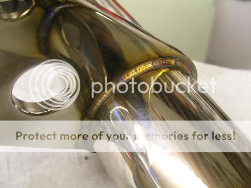
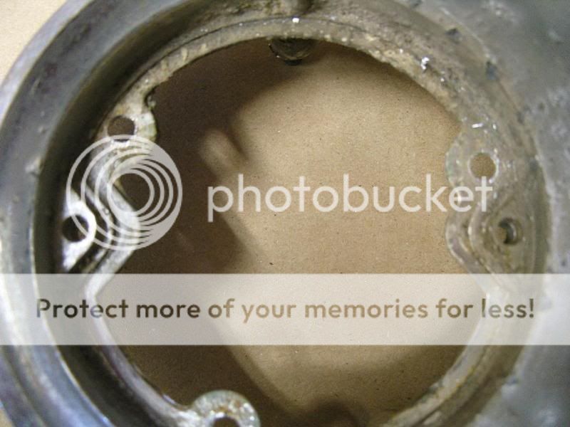
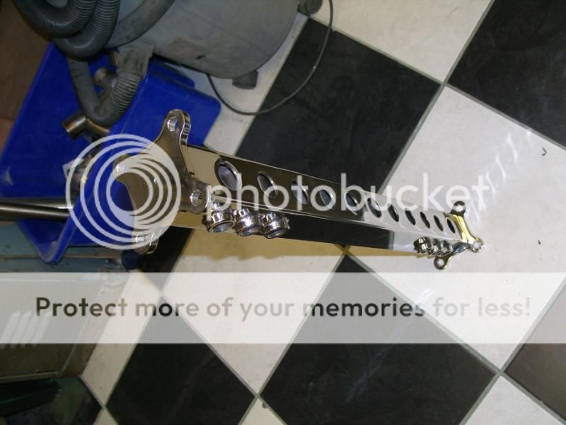
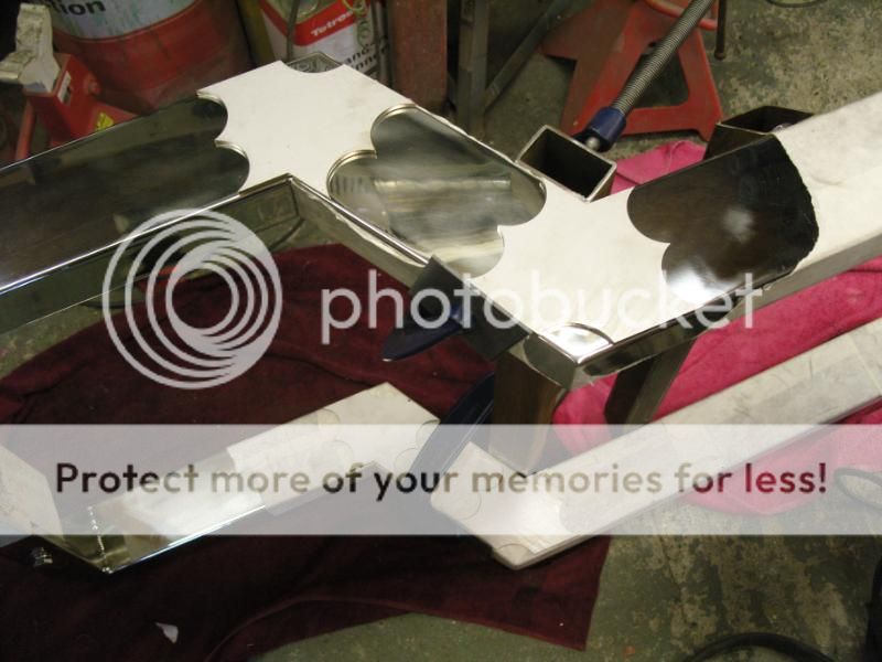
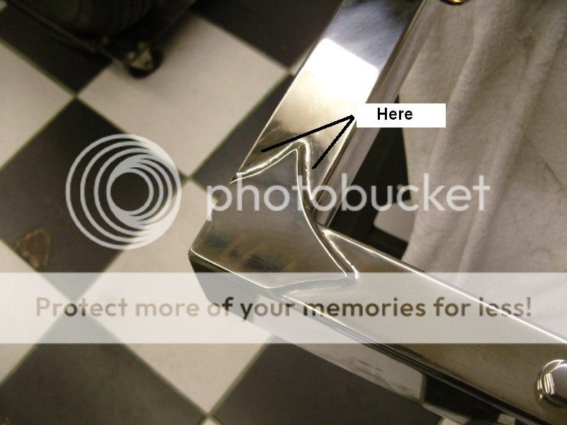
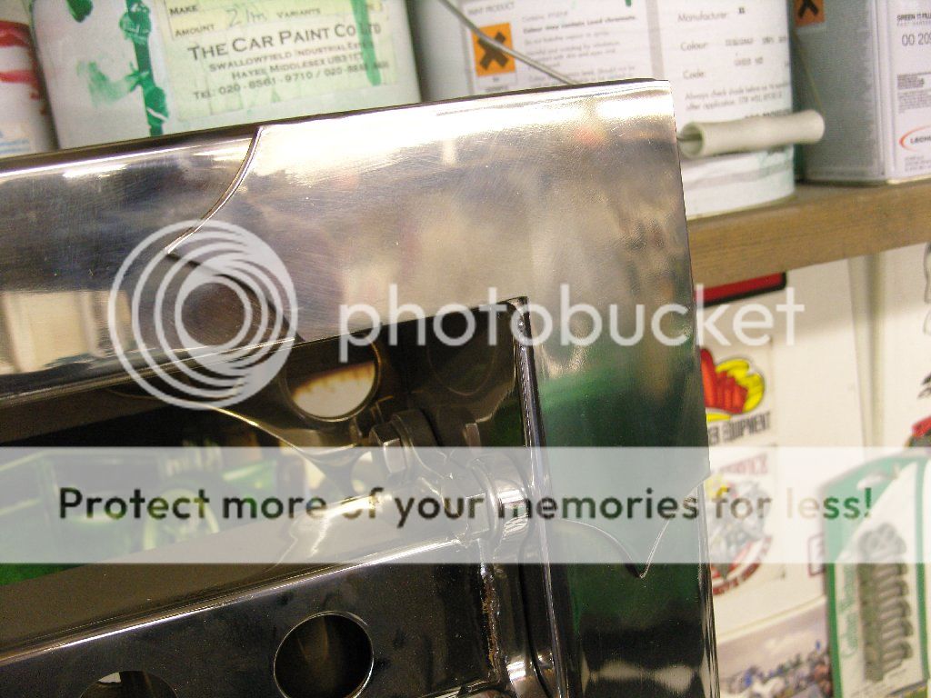
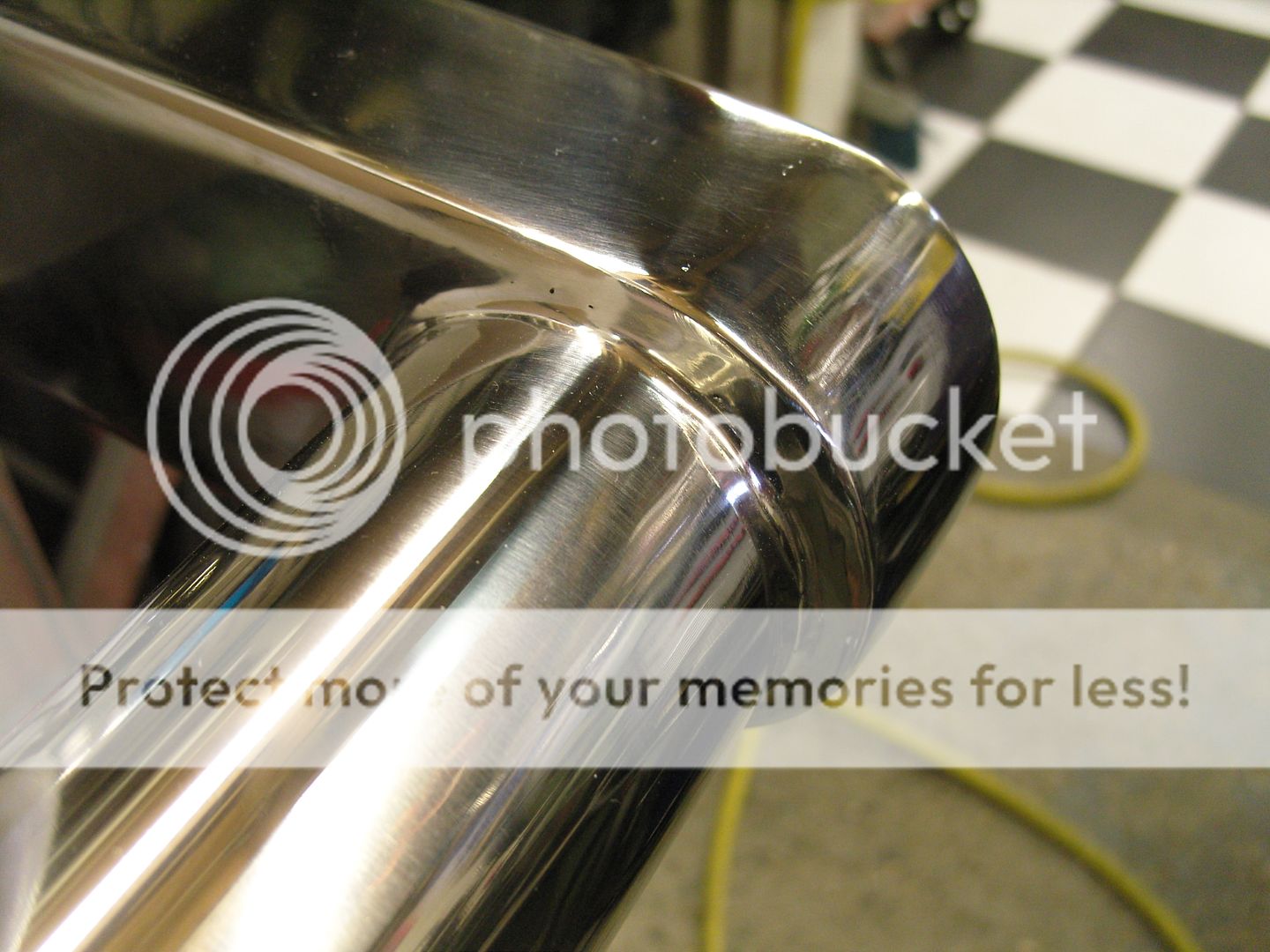
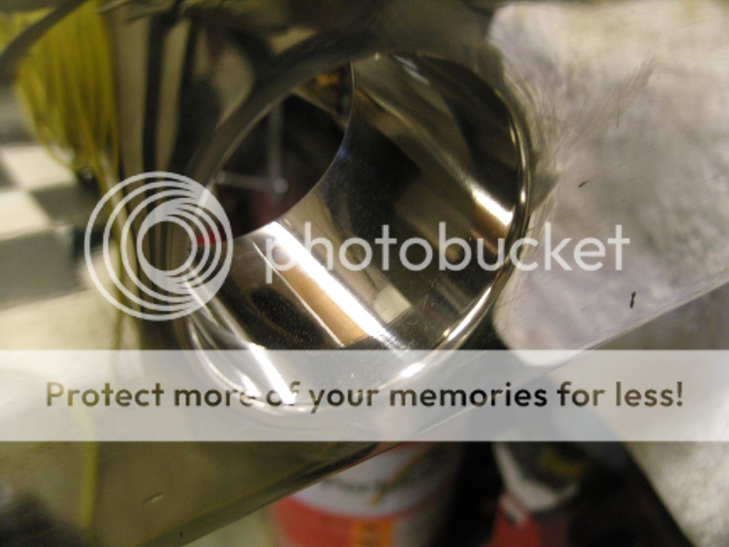
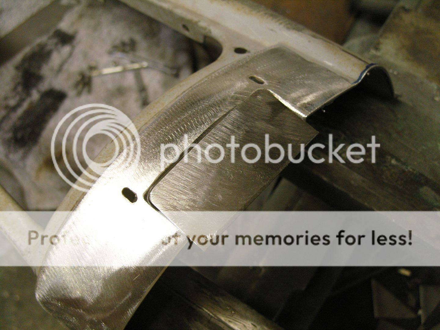
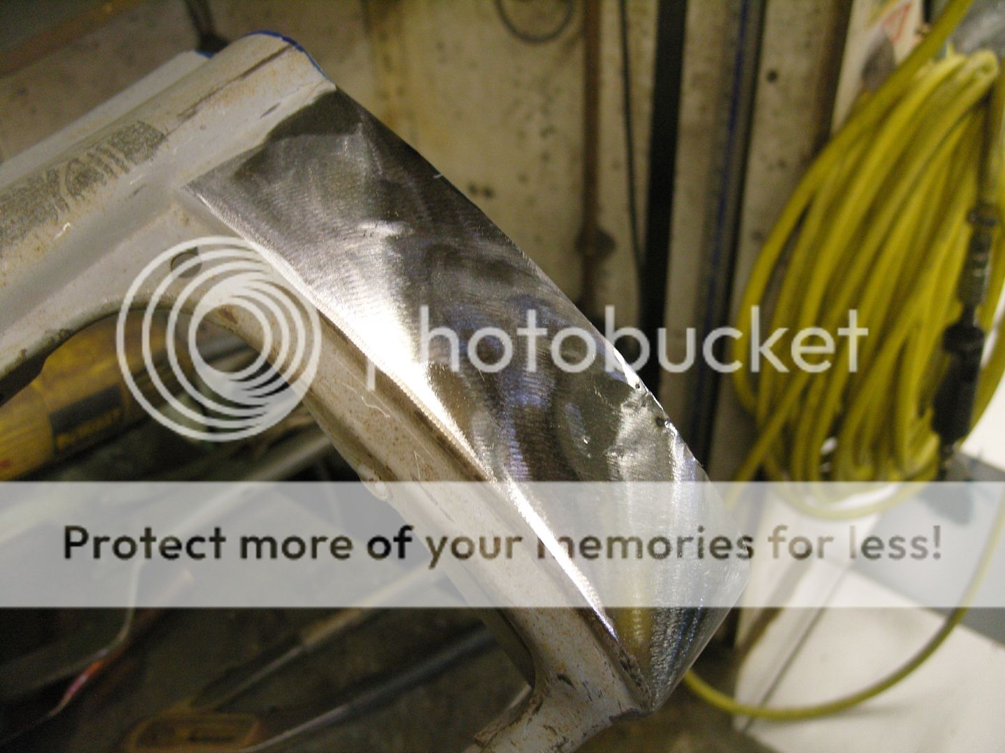
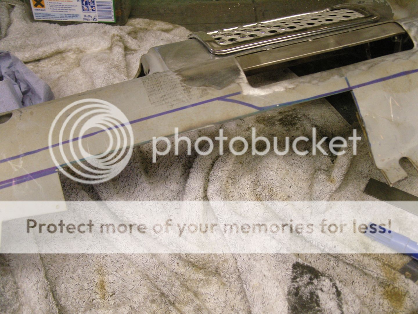
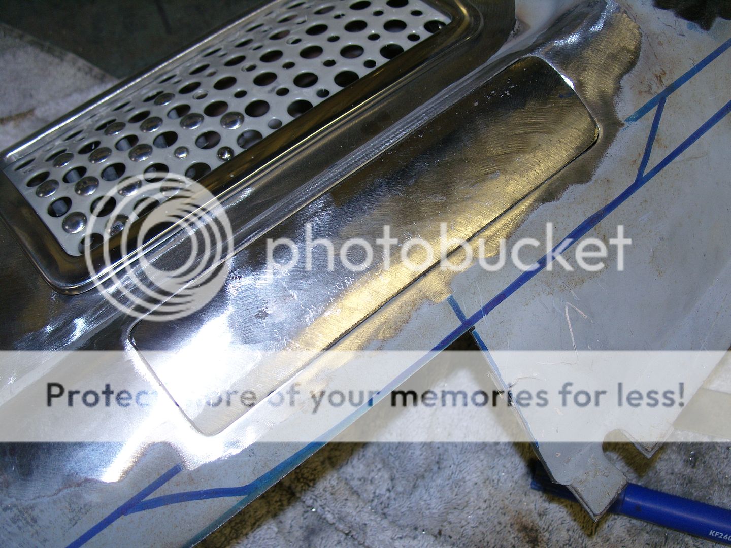
Here the ends have been rounded off to 3", i used 3" x 1/8" wall tube which made the job much easier.
The ends are now boxed off

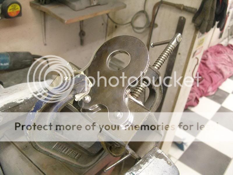
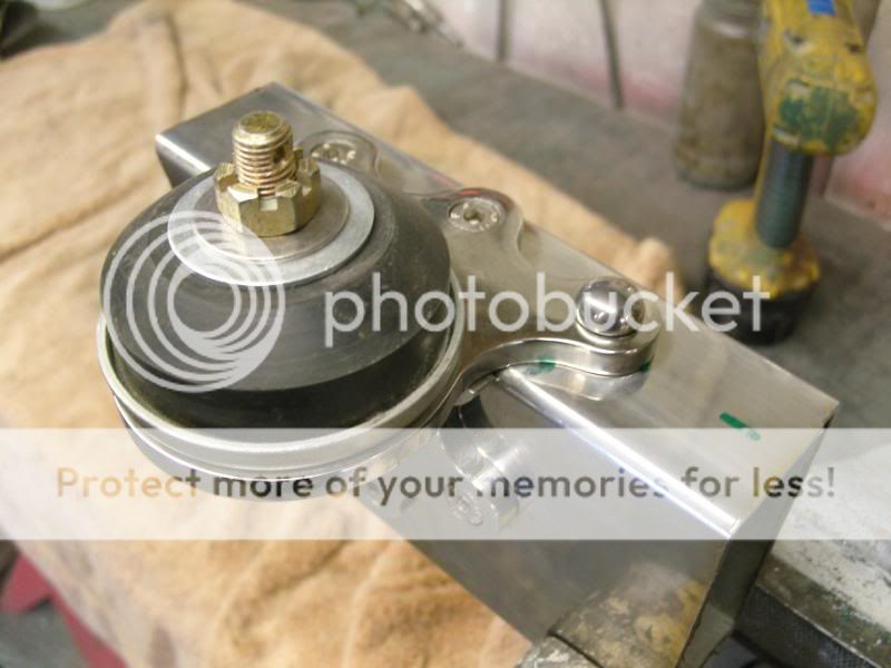
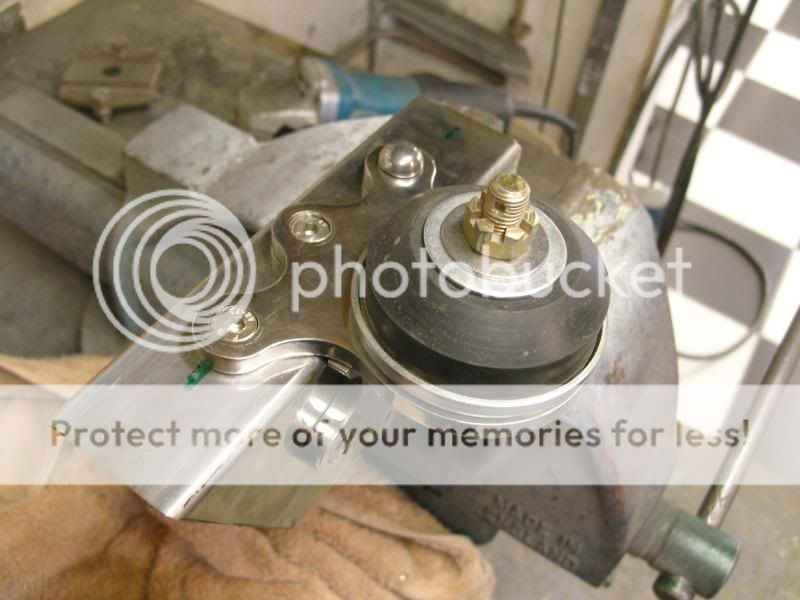
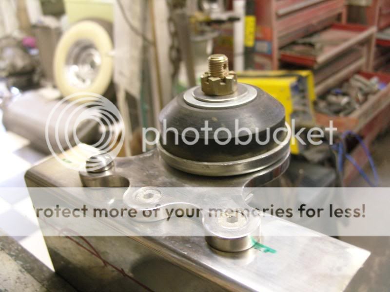
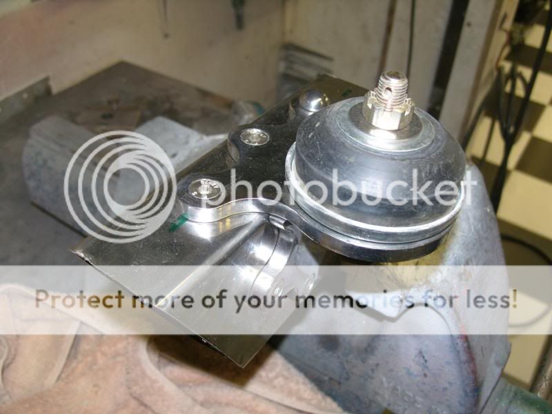
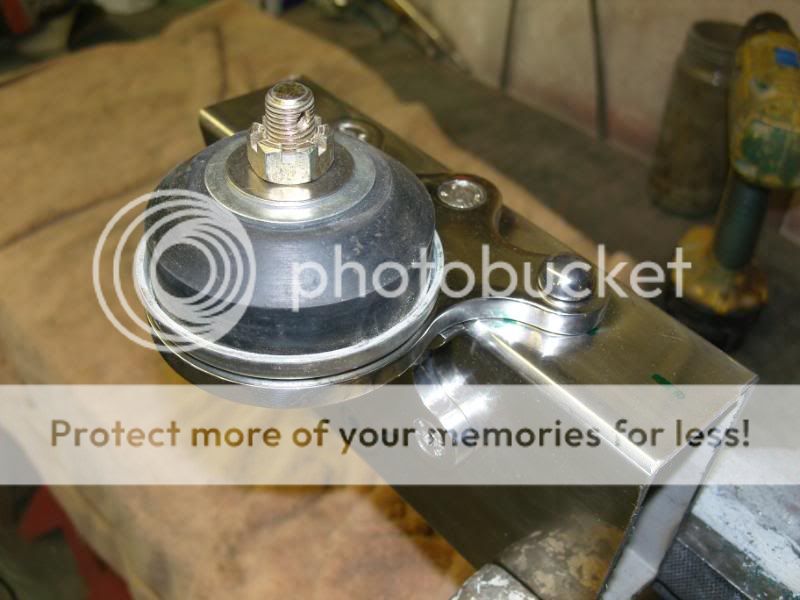
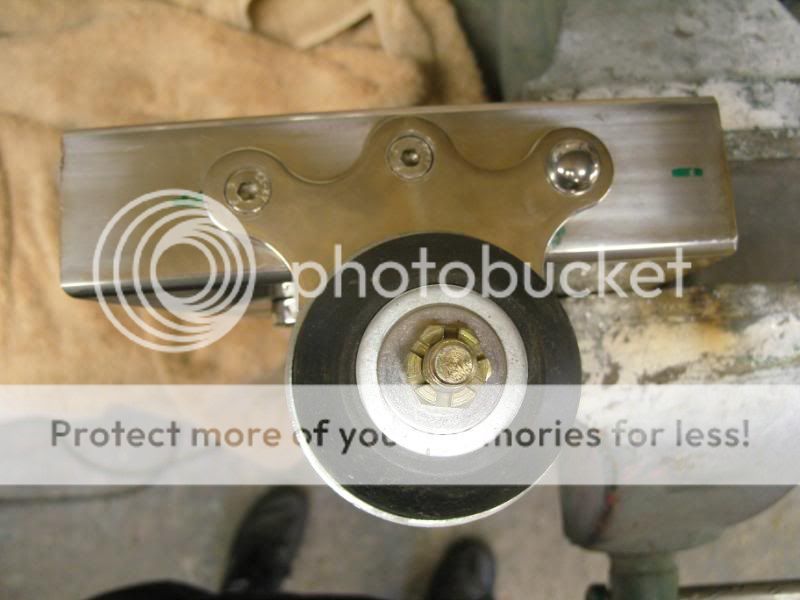
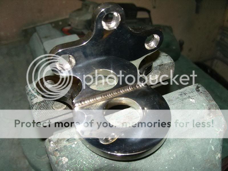
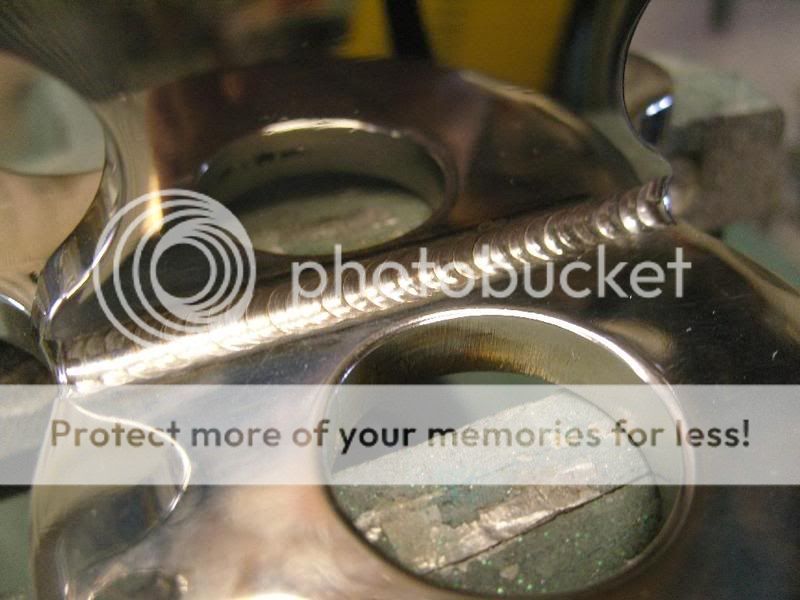
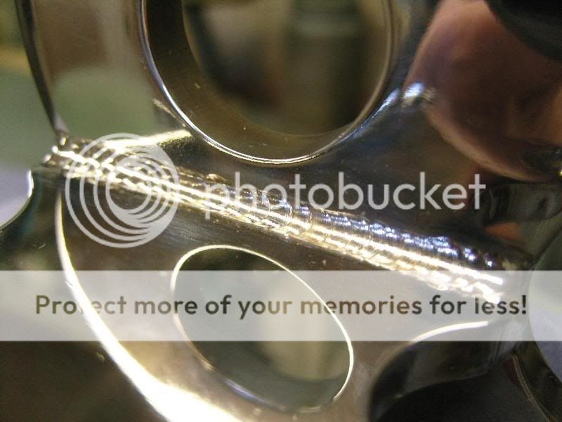
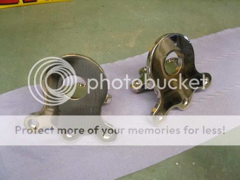
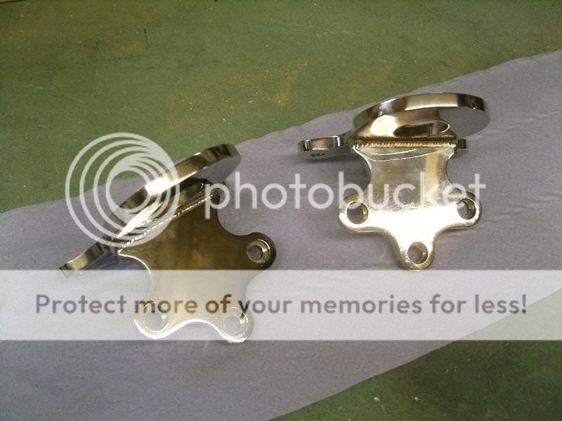
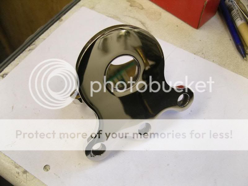
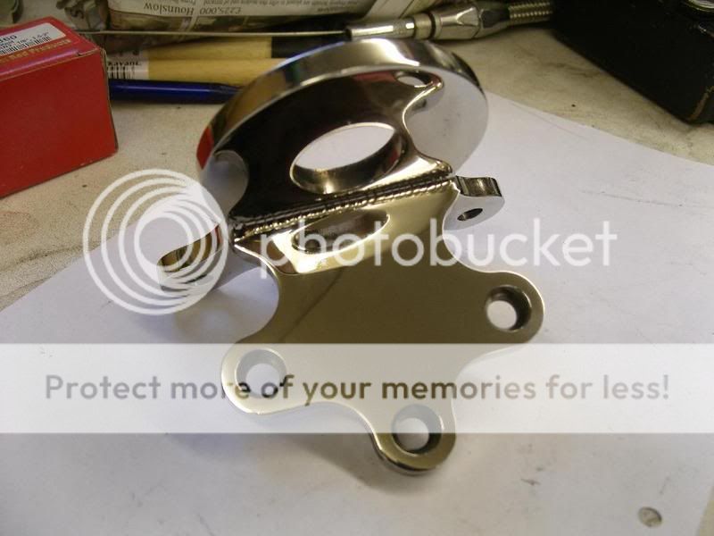
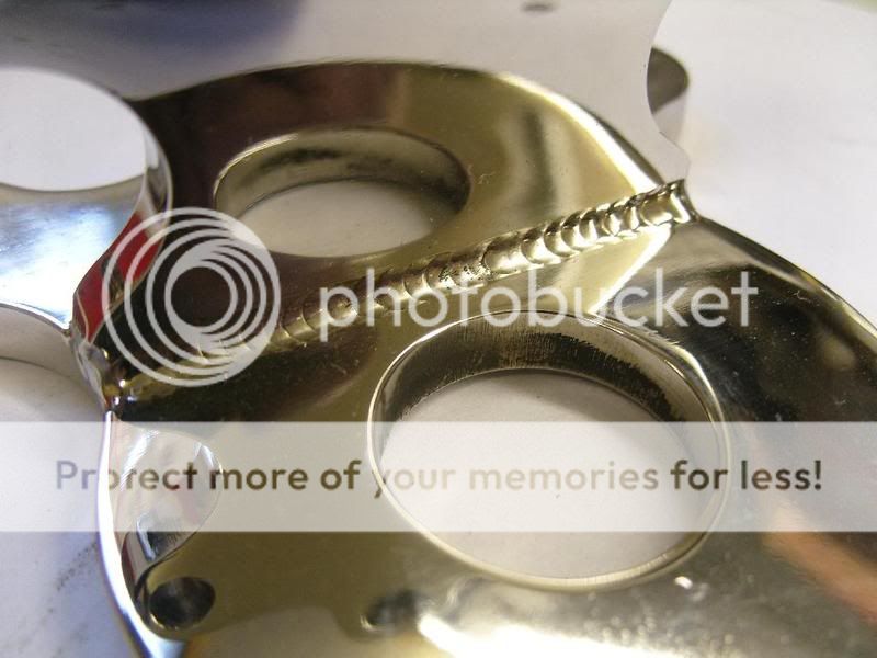
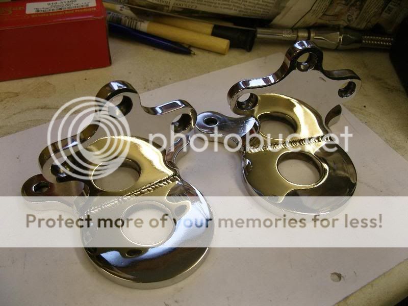
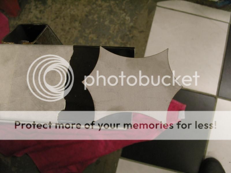
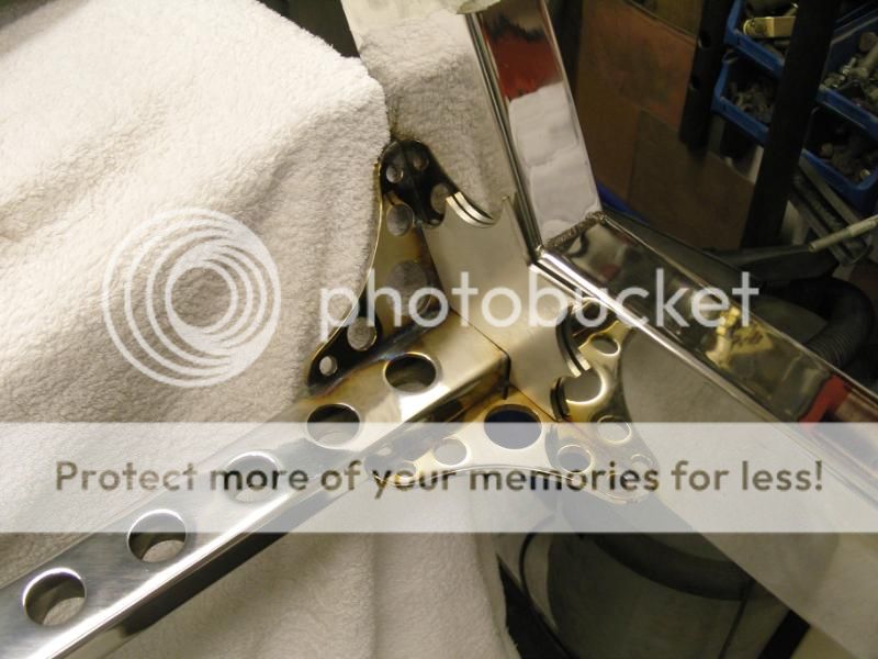
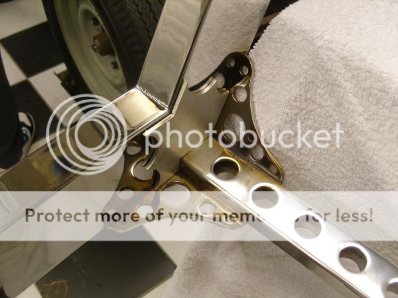
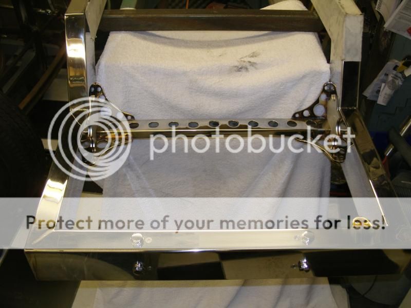
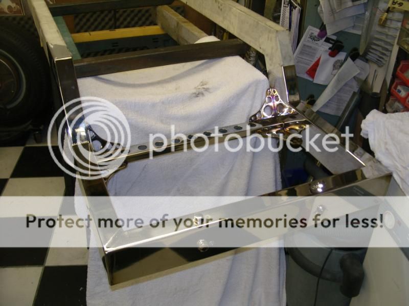
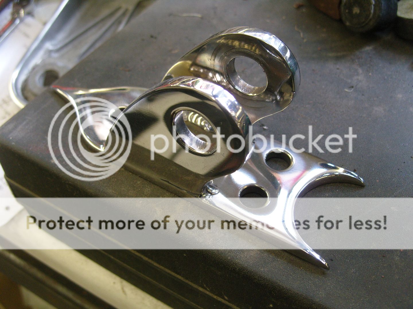
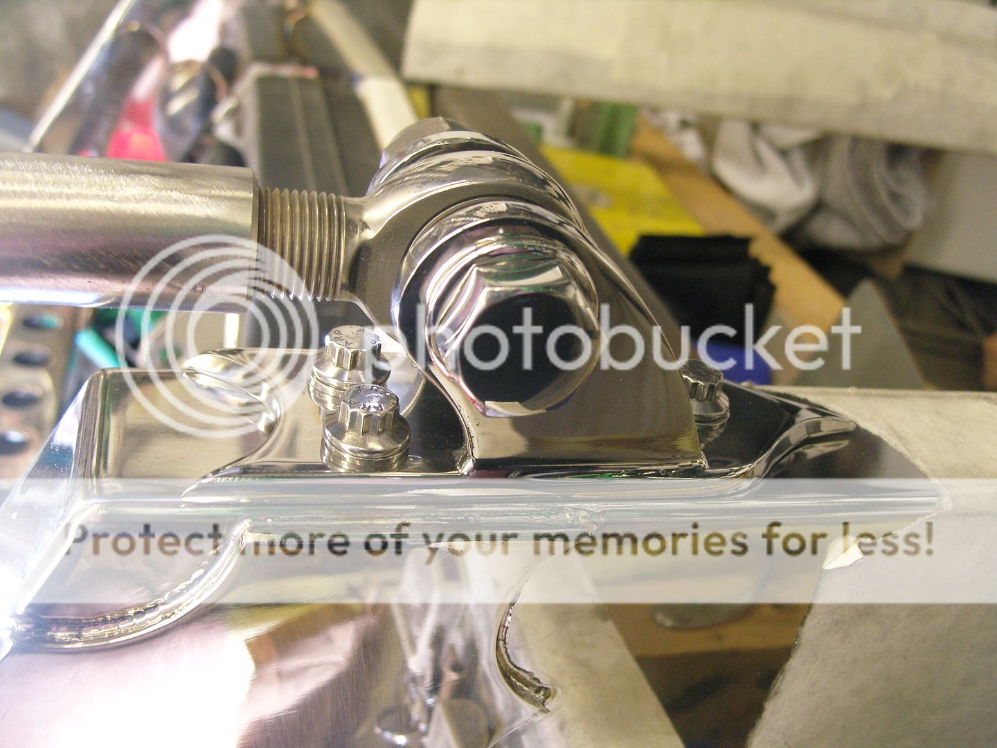
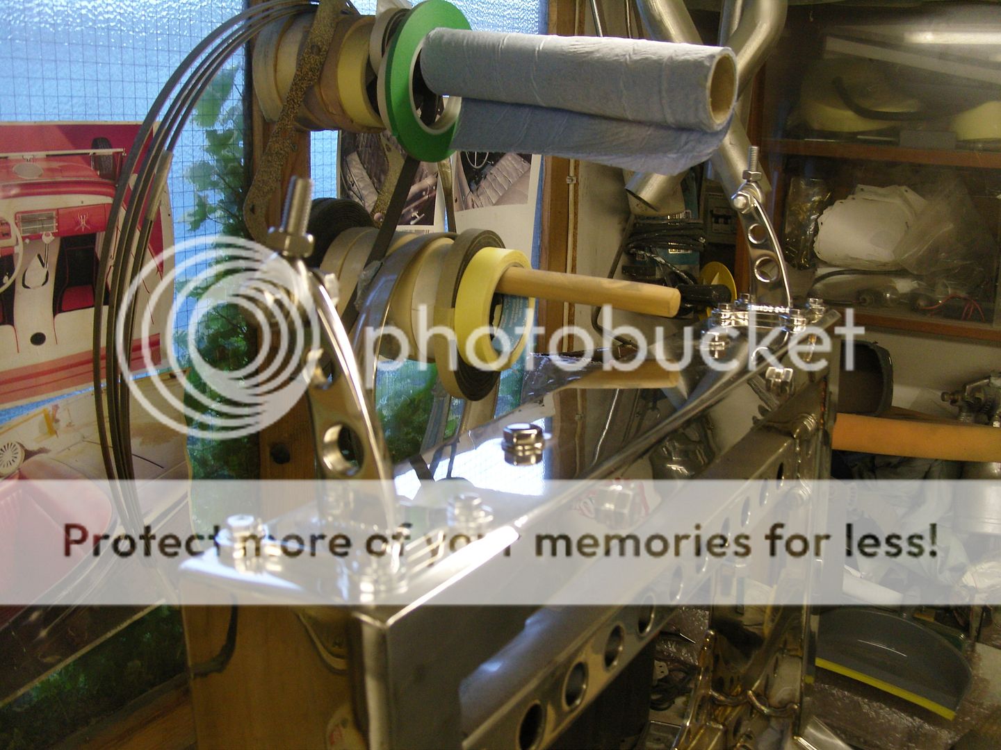
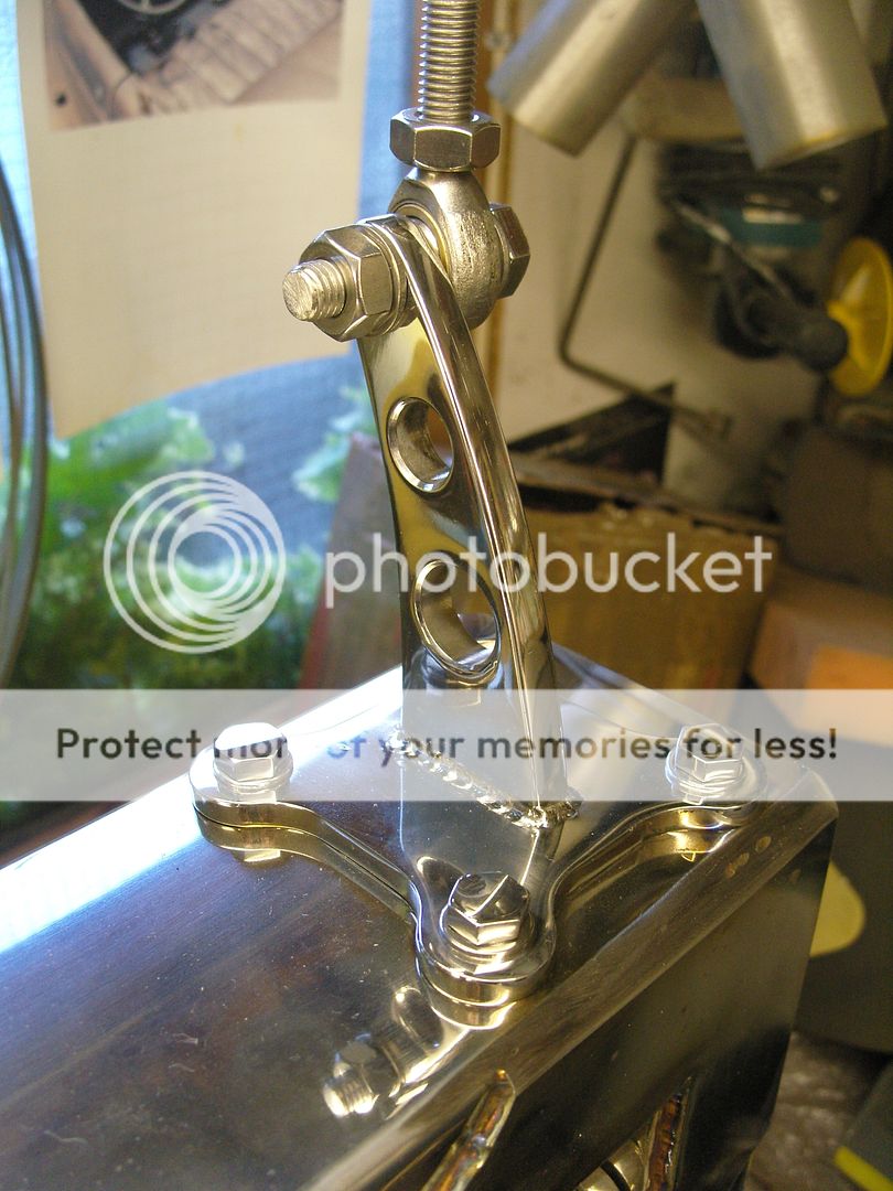
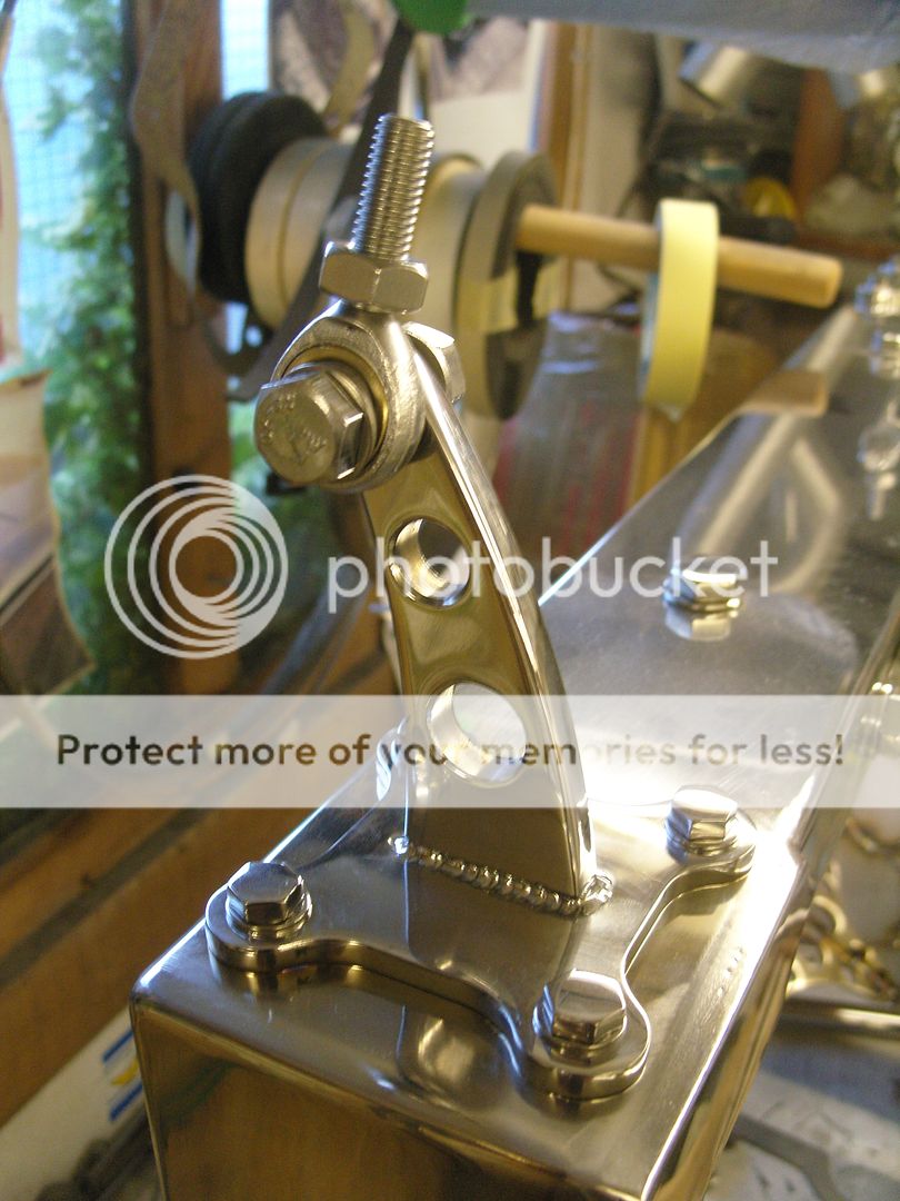
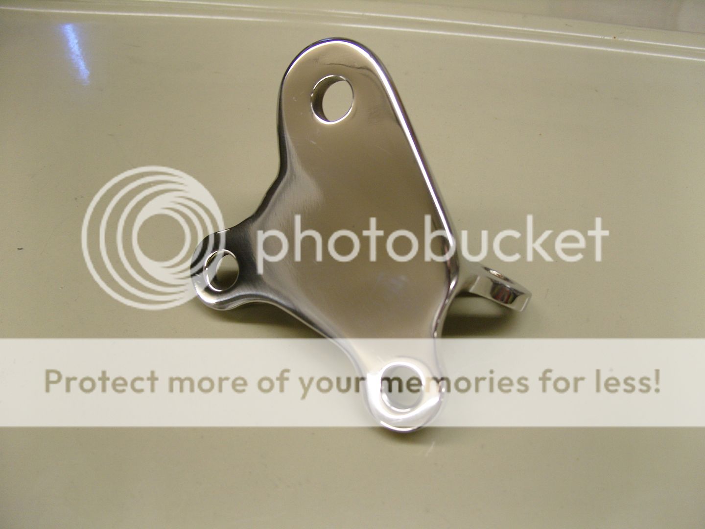
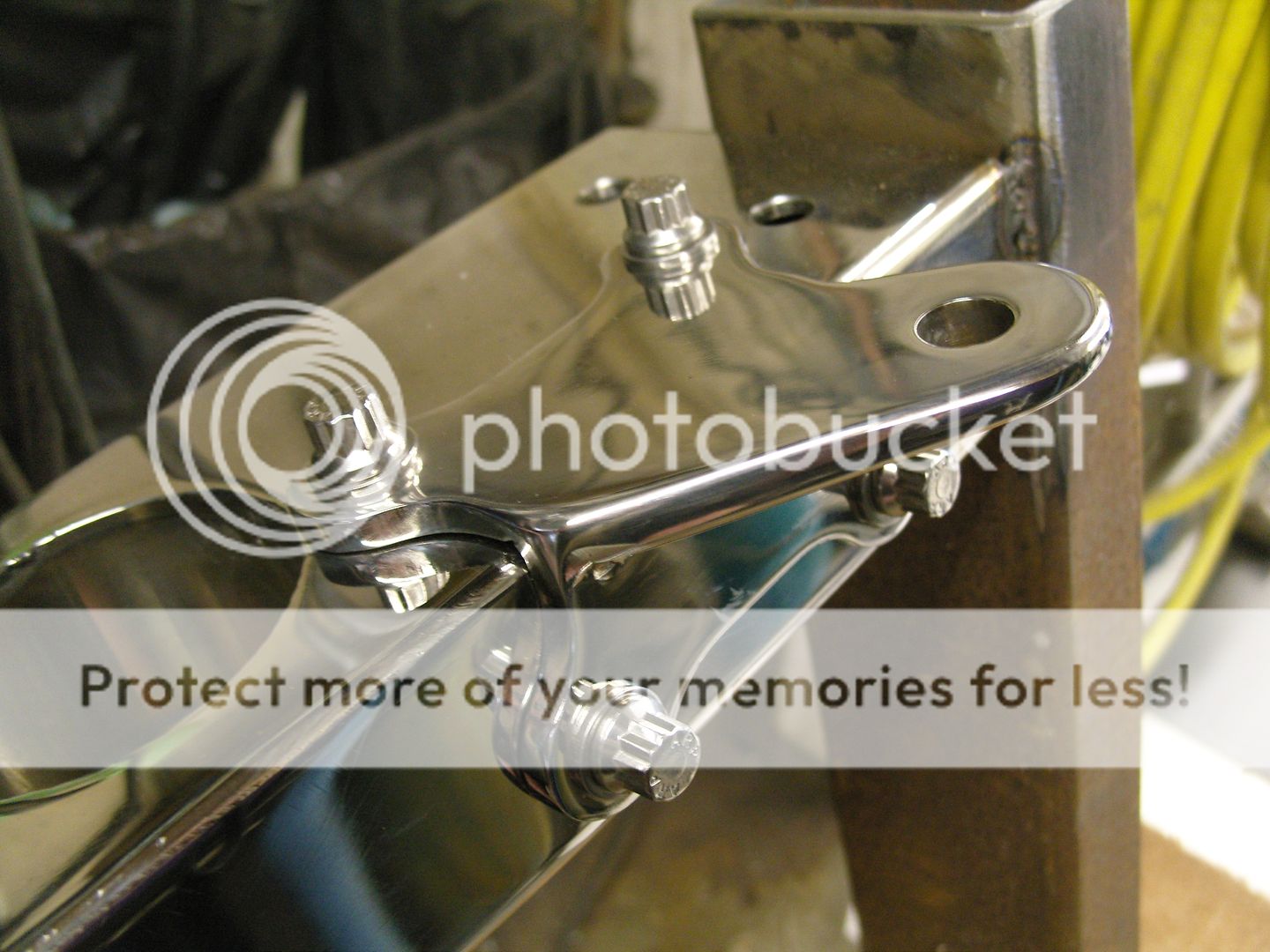
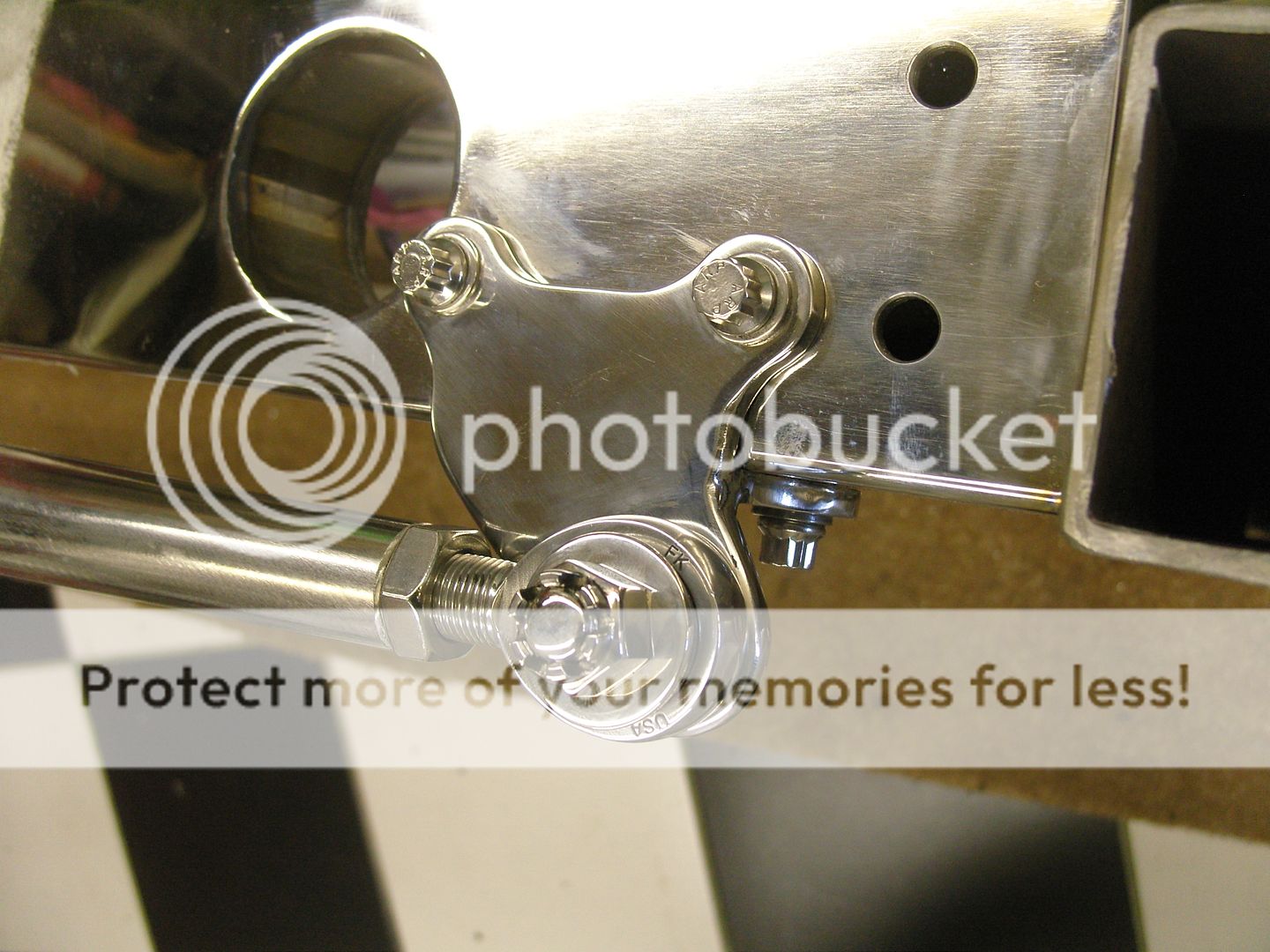
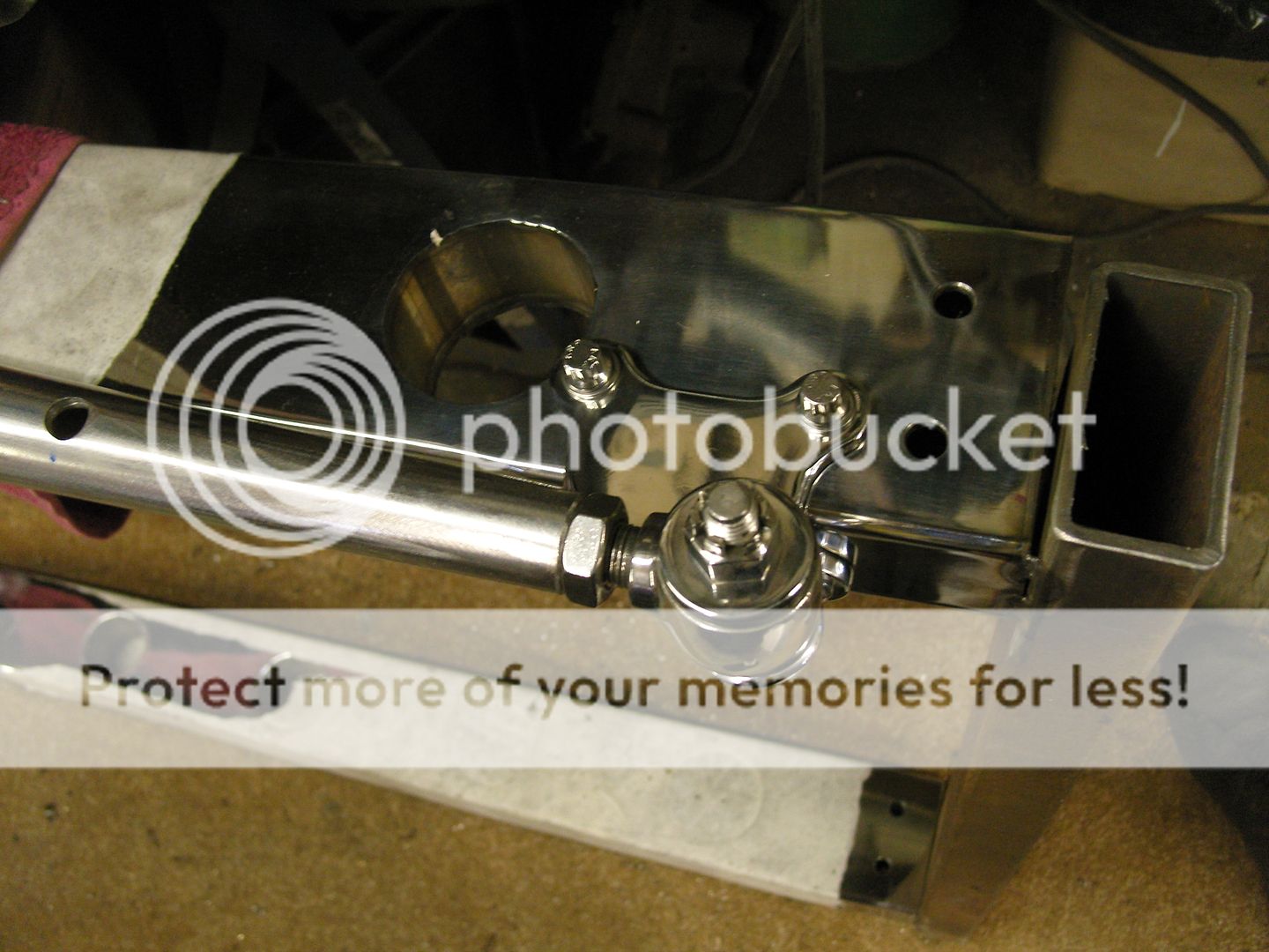
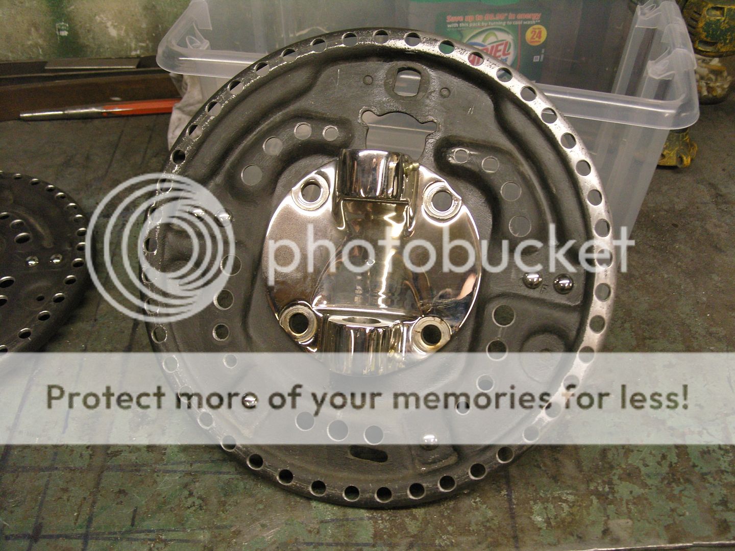
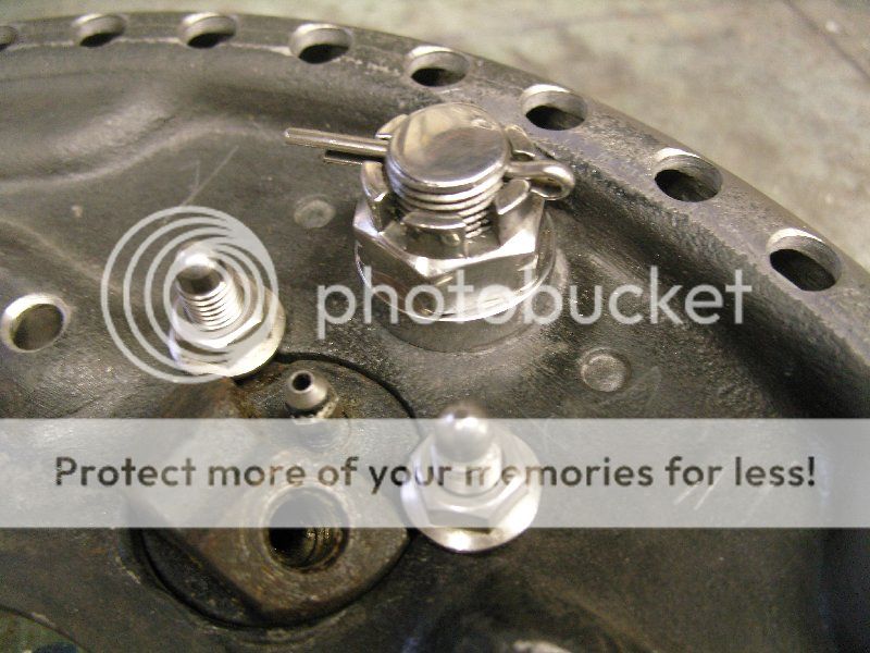
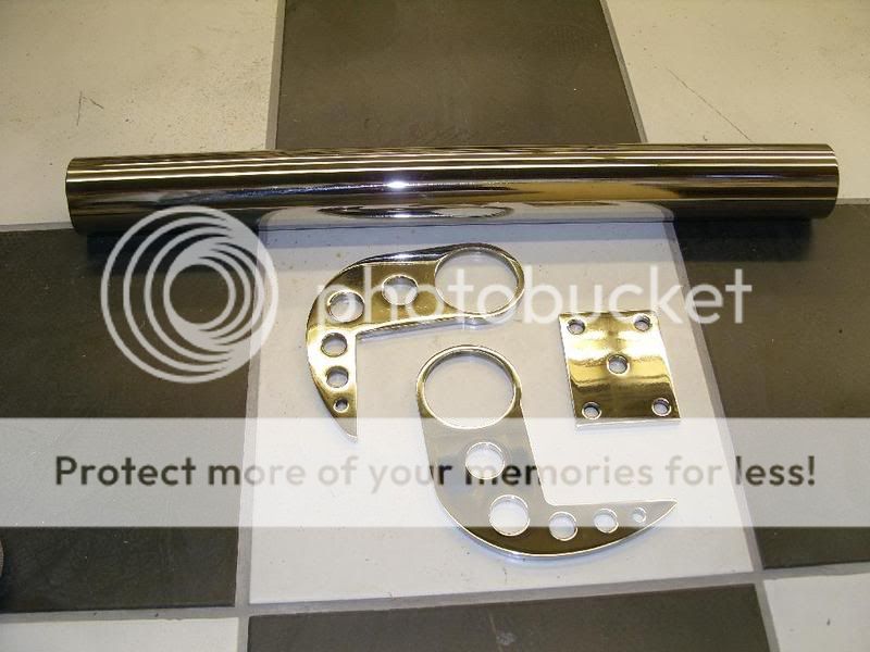
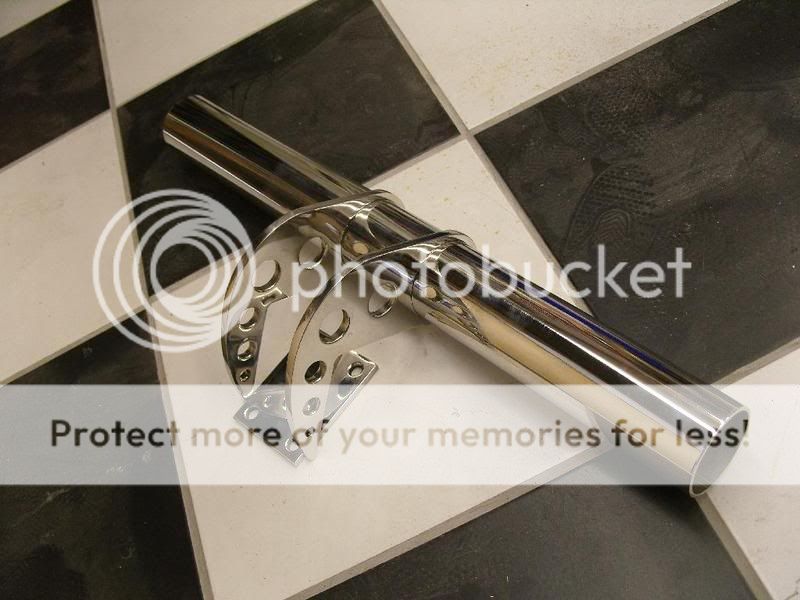
Here are the suicide mount parts polished, Ready to weld together
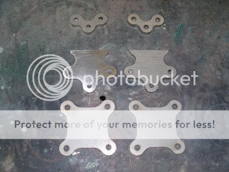
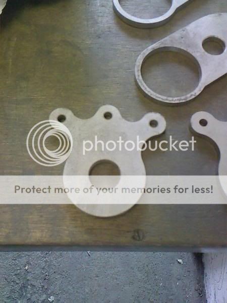
Here are the engine mounts i had laser cut, They will get polished very soon.
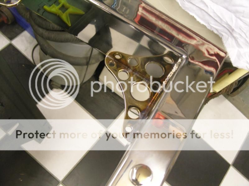
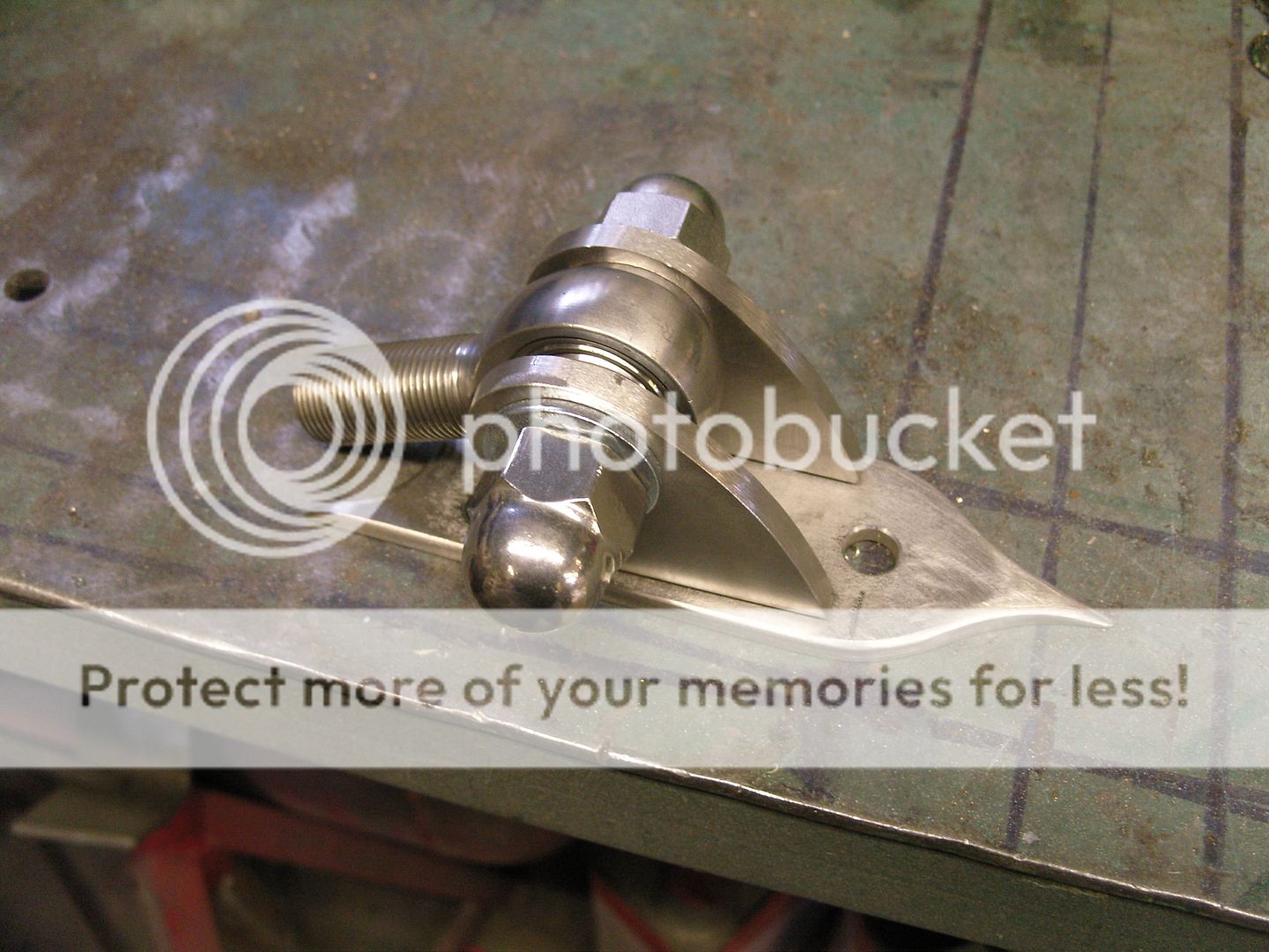
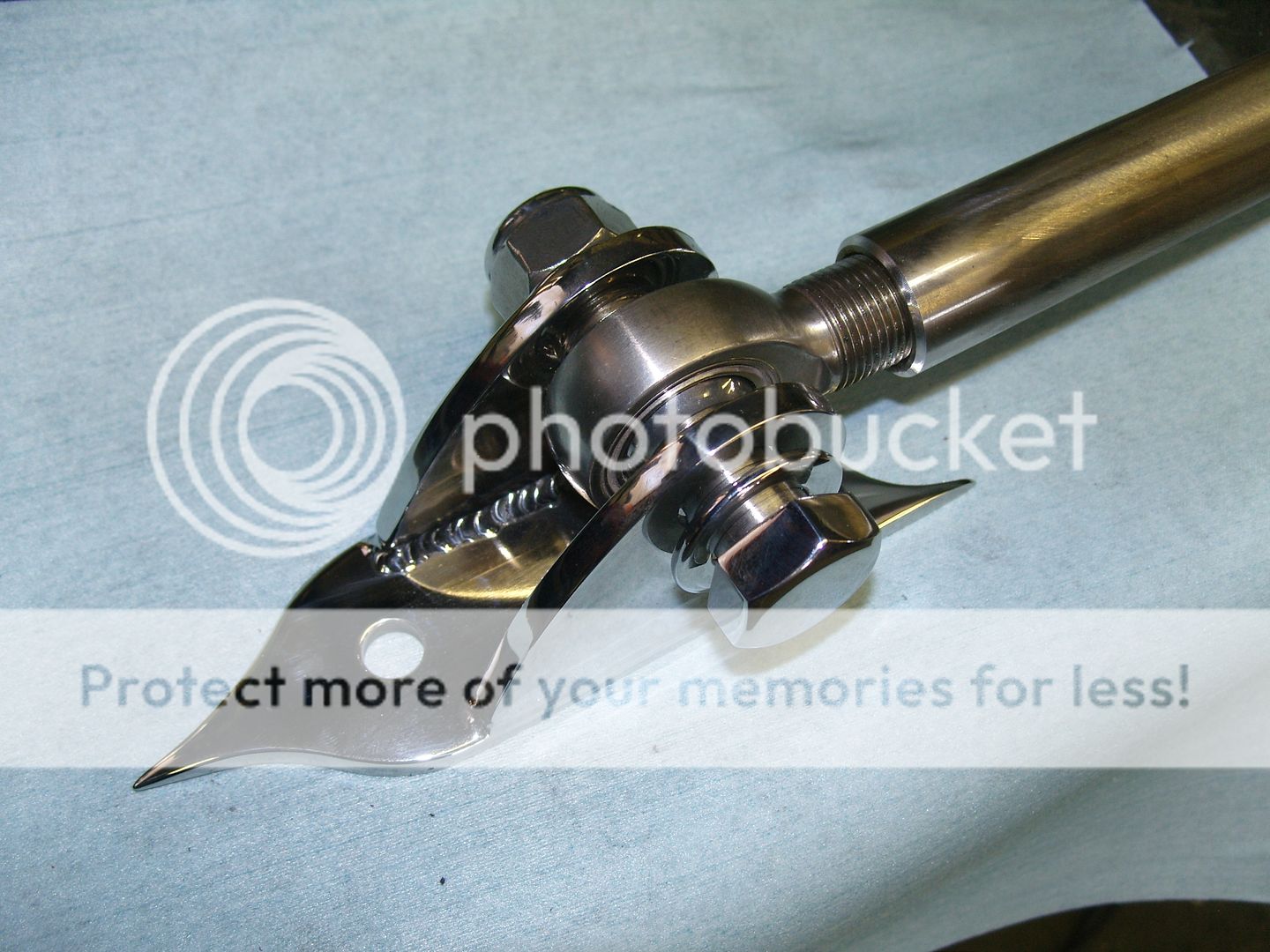
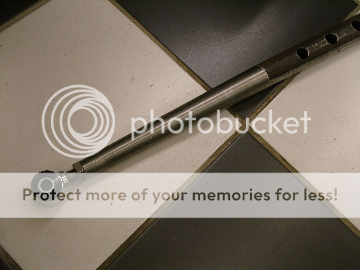
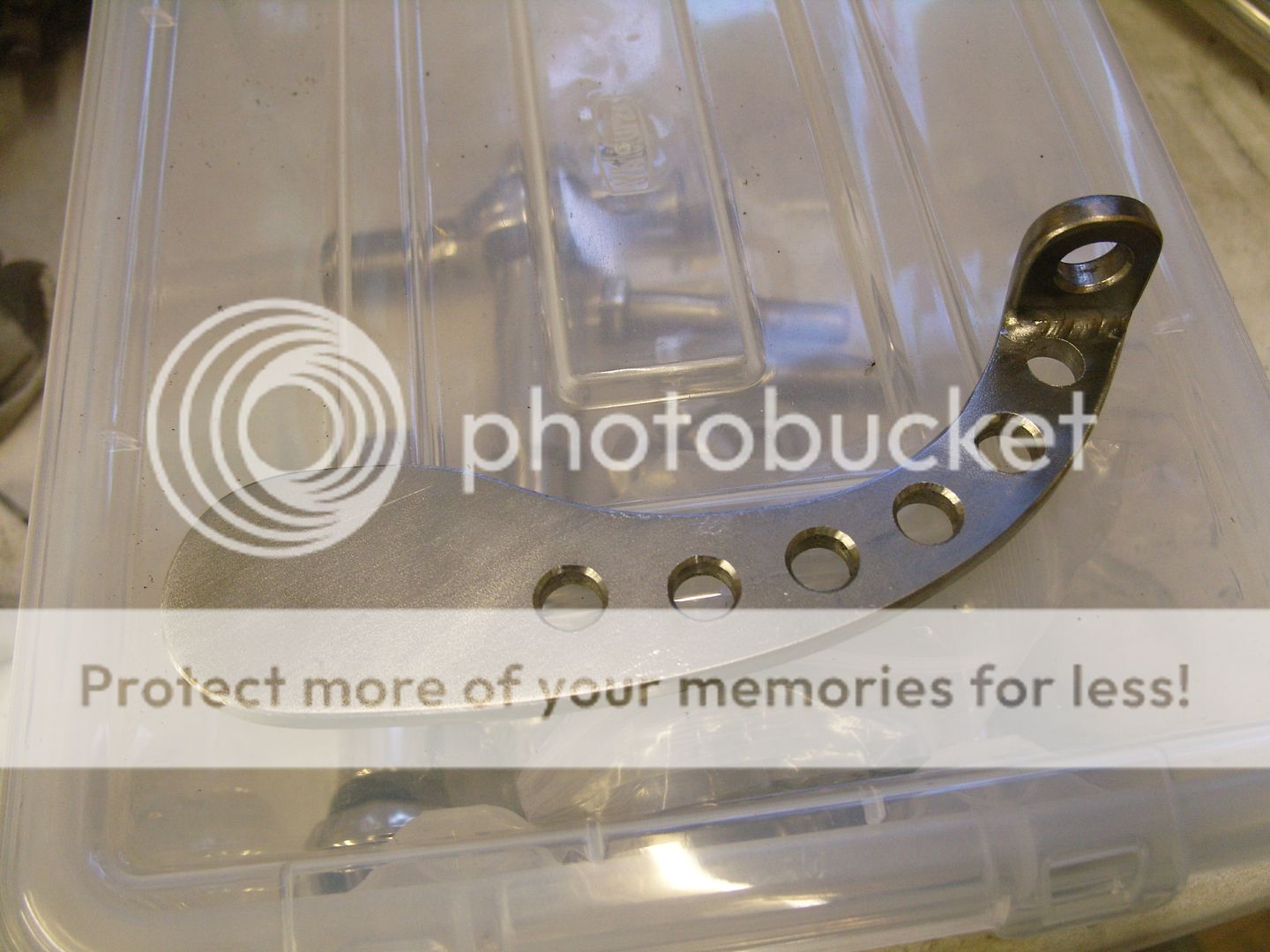
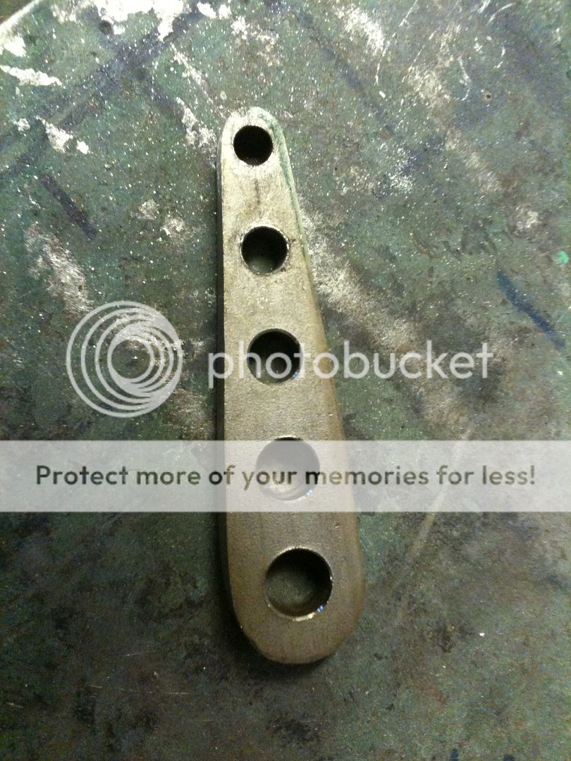
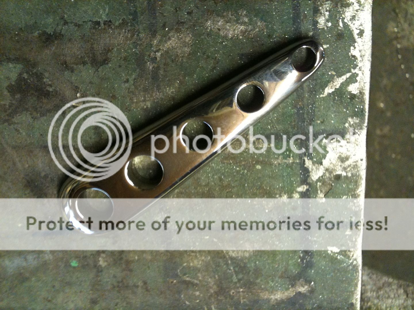
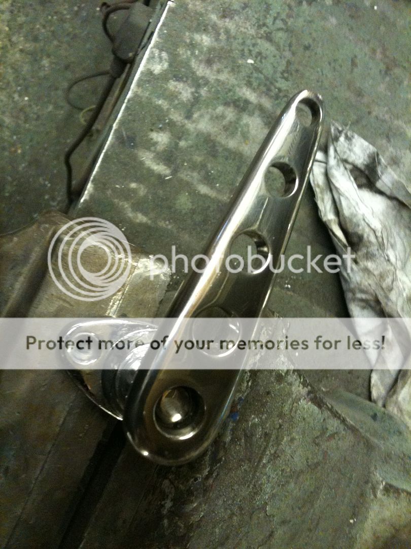
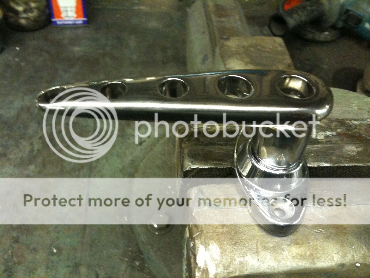
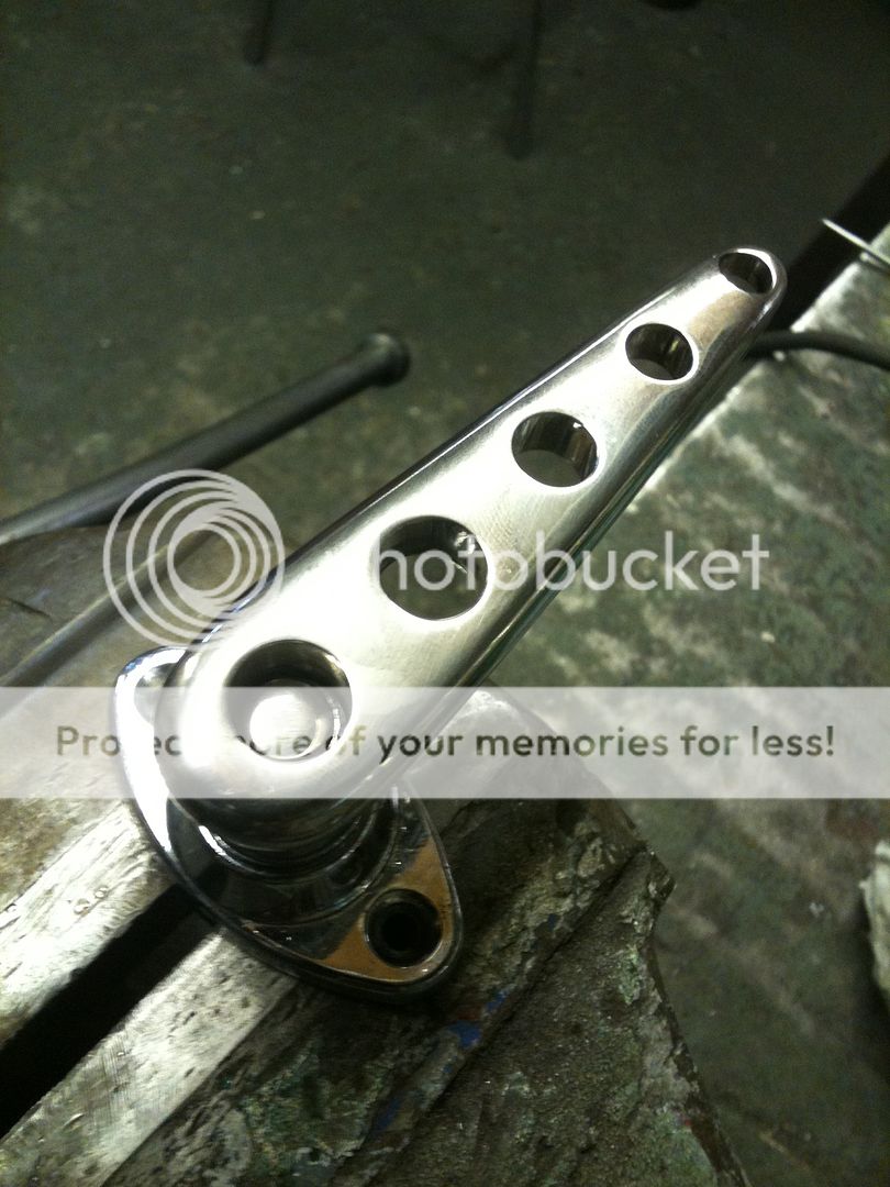
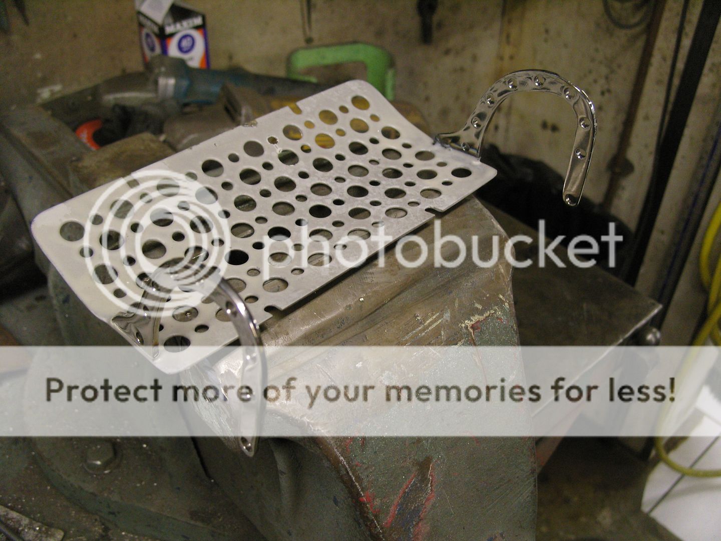
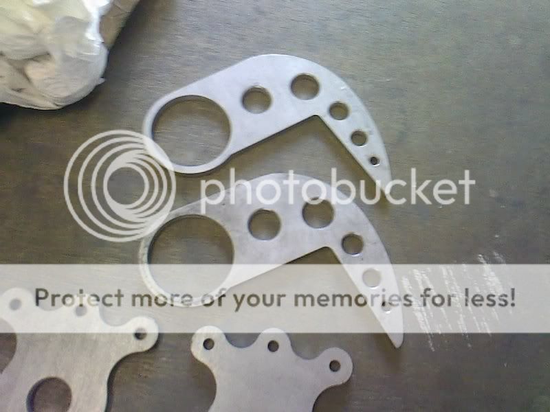
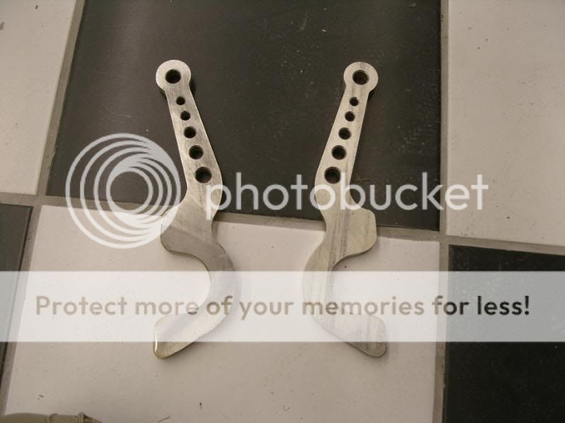
These are the front steering arms that i drew up and had laser cut. I have yet to add the threaded bungs to attach to the spindles. the holes are graduated and were drilled after cutting.
Will update as i progress, Thanks for looking.
Just started collecting parts for a new project, Hopefully my 32 will be soon finished and I'm really getting the urge for some track action again, Was going to uprate my T but it would mean some major modification which would spoil the look to be honest so decided to start afresh.
New project will be a street & strip car and as my T will have crossplys, Body will be channeled 4" over the frame but full height.
I've picked up a 26T Coupe body which will have a heavier duty version of my T chassis under it as the motor is going to be a Cadillac 500ci I picked up, I had a bit of luck as I was going to buy all the parts for the engine from MTS who are one of the Caddy experts but when I joined their forum I managed to pick up all the parts for the engine from a guy in the states as brand new parts still in the boxes 30% cheaper than new
Engine should end up at 500+ cubic inches and has the following spec
10-1 Keith Black +60 pistons
Scat forged rods
MT20 very lairy Cam
MTS Valve train conversion
MTS Heads
Edelbrock ported intake
Edelbrock EPS 830 carb
Full balance
Cloyes heavy duty timing chain
2" Headers
Art Carr TH400 with transbake (Thanks Crusty)
B&M 2200 stall convertor
My aim is to build a 60's style T again with Radir Tri ribs, Copper metalflake paint & a White fur interior !!! Hope to run very low 11's or maybe high 10's on crossplys, Maybe more on slicks.
I'm aiming for this kind of look but with Copper flake and obviously a 26T body
Here's a few pics of the used body i bought
Here it is mocked up on a friends frame, This is very much how mine will look.
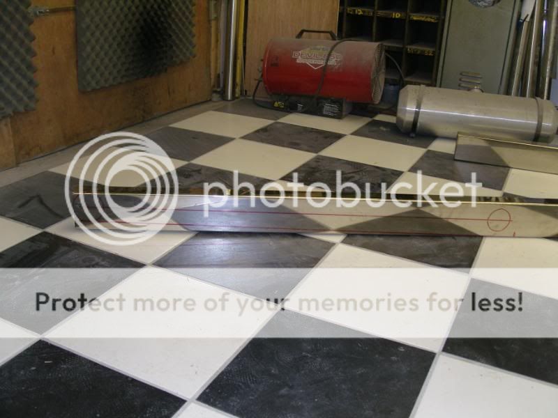
Sue has been telling me to move the 6metre length of polished 100mm x 50mm stainless box from the side of the house, wasn't quite sure where to put it so decided to cut it up to size, I got a bit carried away and ended up making the side frame rails, still save having to do it later !!!
This is what i started with.
This is the front suicide mount which i drew up and had laser cut.
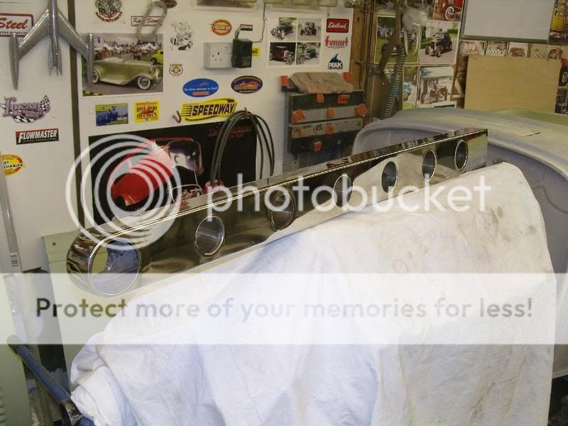
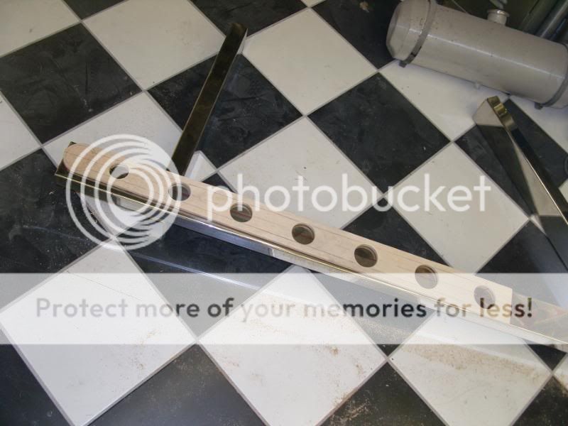
Here the side frame rails are marked out, the chassis design is the same as my 23T but i've goneup a size on the box as the Caddy motor has twice as much BHP and Torque as the 23T. The 100mm x 50mm looks very klunky on the front of a T so from the firewall forward will taper to 3". Side rails also taper in from the firewall 3 degree's
Here's the mockup in Ply
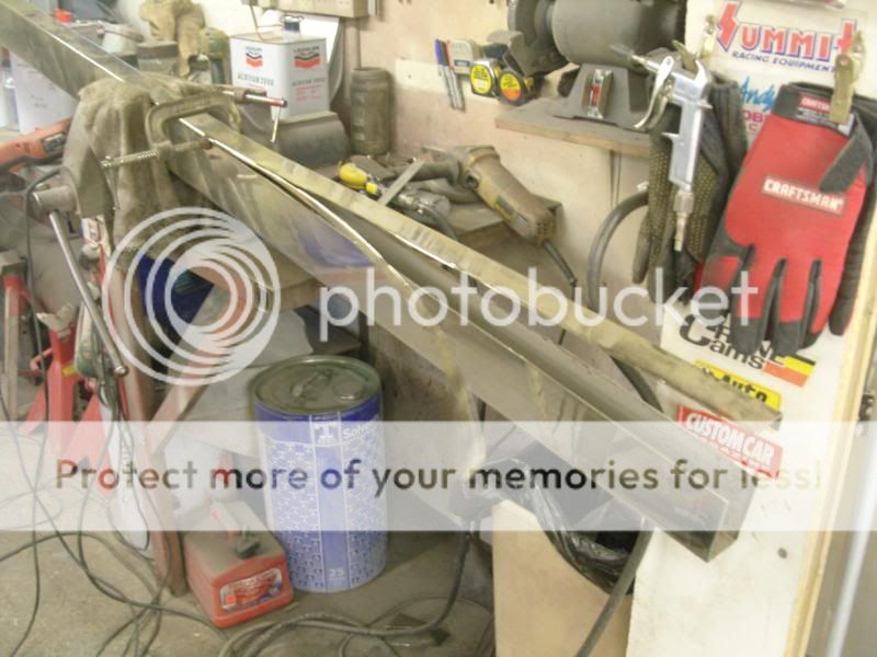
Once i had the side rails marked out it was time to get the 9" grinder out which was fitted with a 1mm stainless cutting disc and the sides were sliced. once i had finished cutting i noticed that the sides of the box had moved all over the place, this will be corrected with clamps before tack welding.
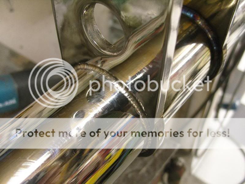
Here is the side rail being clamped back together and tack welded.
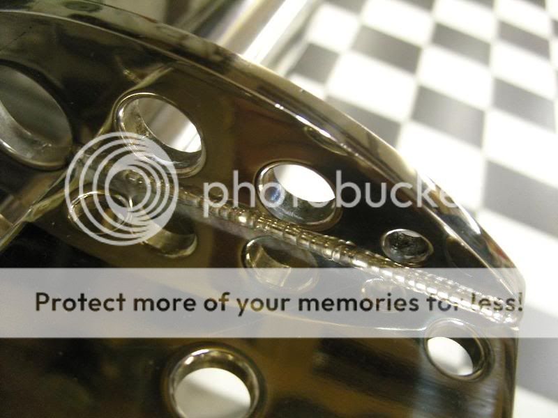
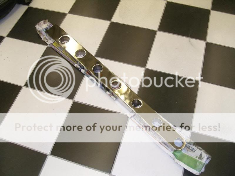
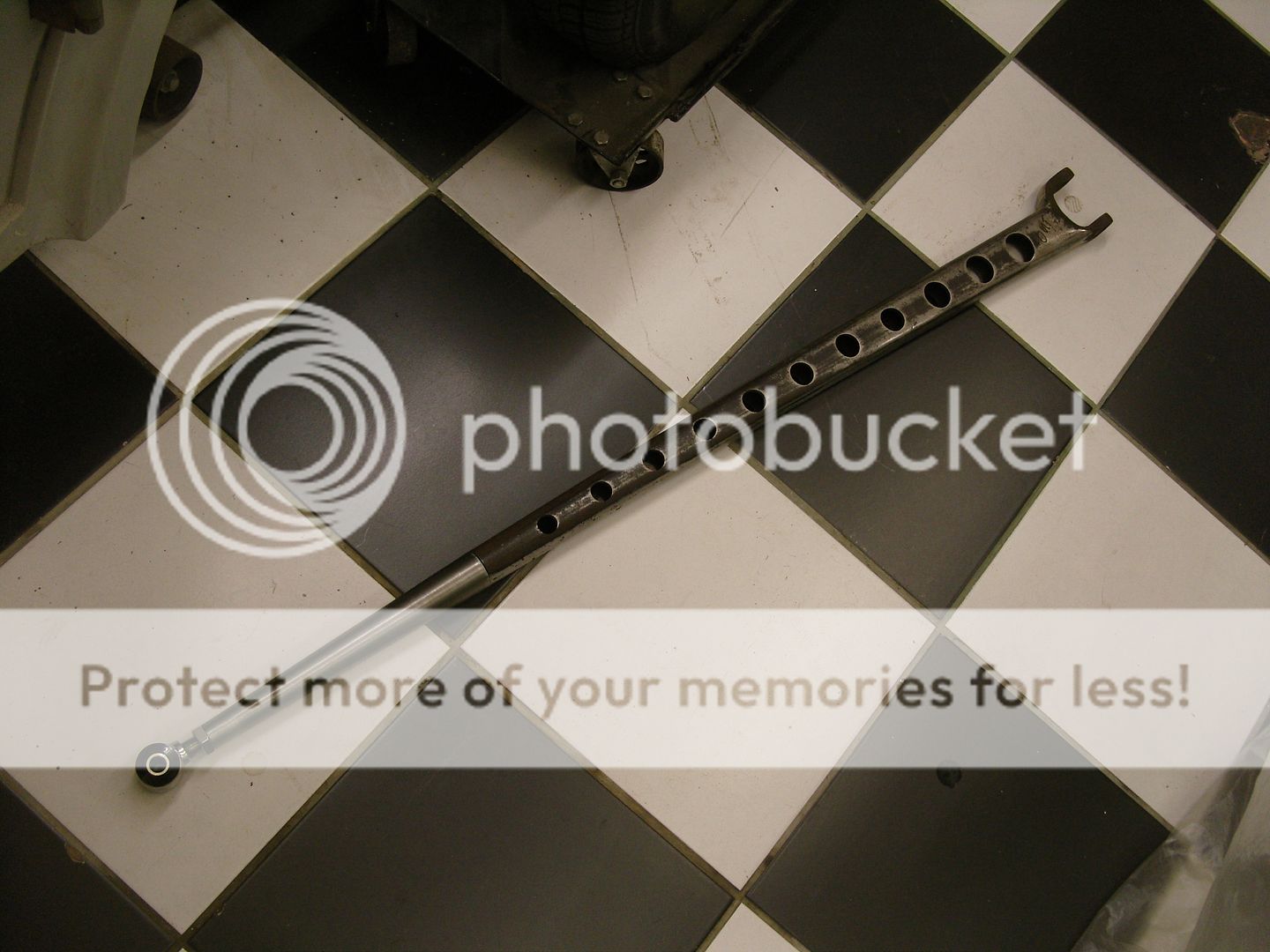
Here i'm marking out the lightning holes in the side rail, they are graduated to suit the taper and will be sleeved
Holes were cut with a selection of good quality hole saws, they cut perfect holes out quite easily, i used 1/8" wall tubing to sleeve them but due to the holes being graduated some are not available in stock size so i will turn the odd sizes on the lathe.
Here the ends have been rounded off to 3", i used 3" x 1/8" wall tube which made the job much easier.
The ends are now boxed off
Here are the suicide mount parts polished, Ready to weld together
Here are the engine mounts i had laser cut, They will get polished very soon.
These are the front steering arms that i drew up and had laser cut. I have yet to add the threaded bungs to attach to the spindles. the holes are graduated and were drilled after cutting.
Will update as i progress, Thanks for looking.