Ron Pope Motorsports                California Custom Roadsters               

My 26T Coupe build

Once i finished the door handles i realised that i would need some matching door mirrors, found some the right shape but when i drilled the mirror arm the die cast was aweful, so decided to make some.

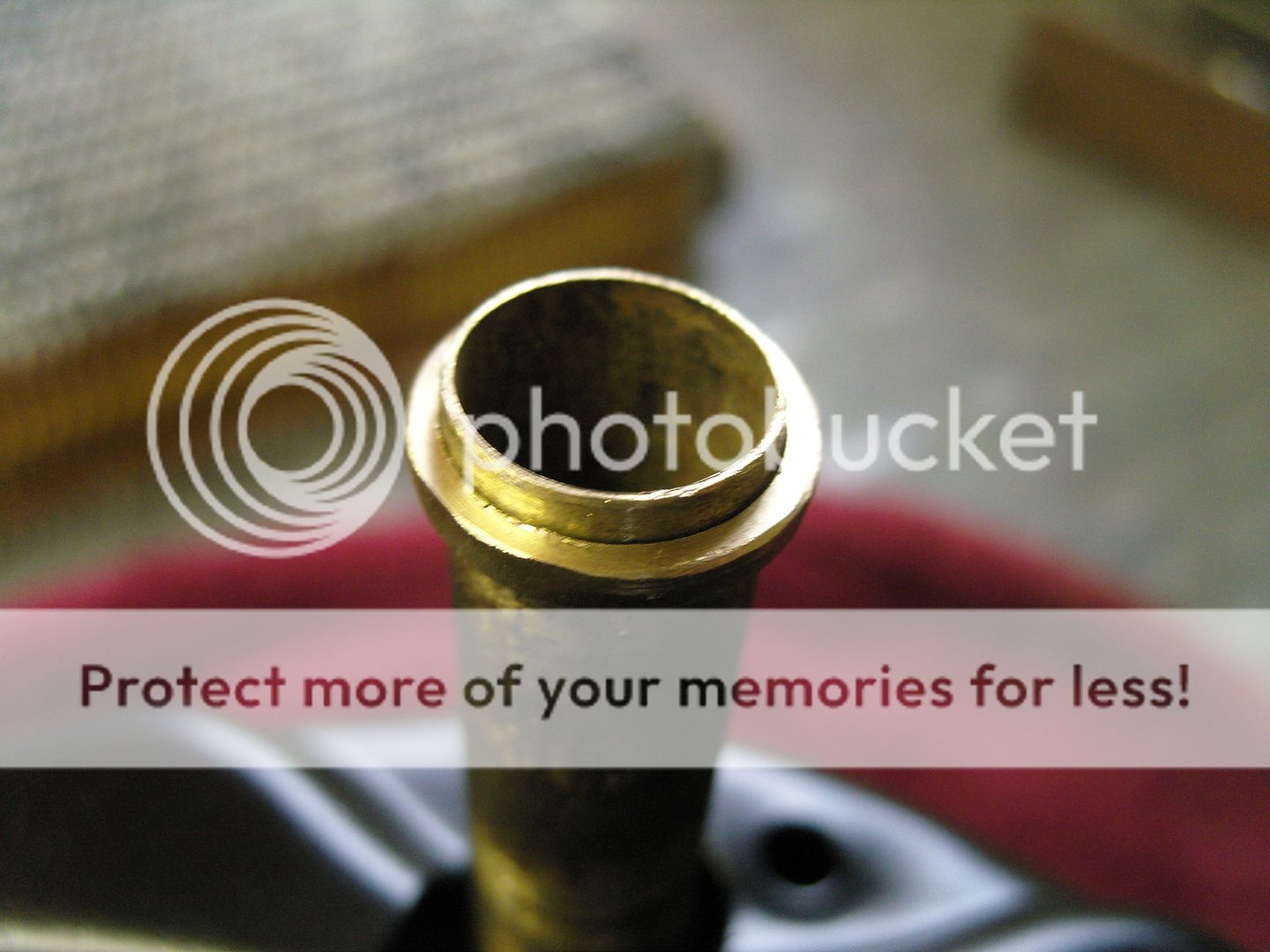
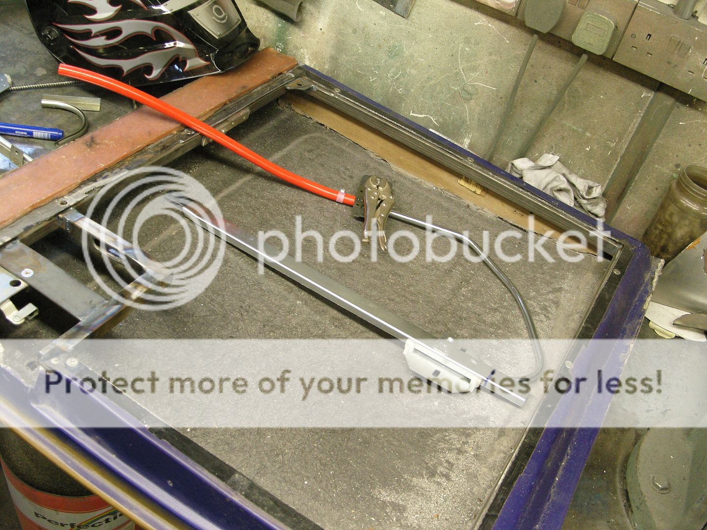
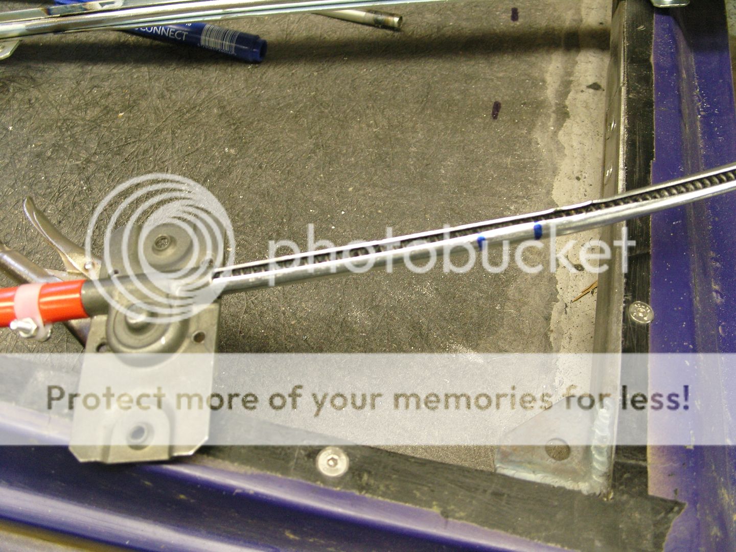
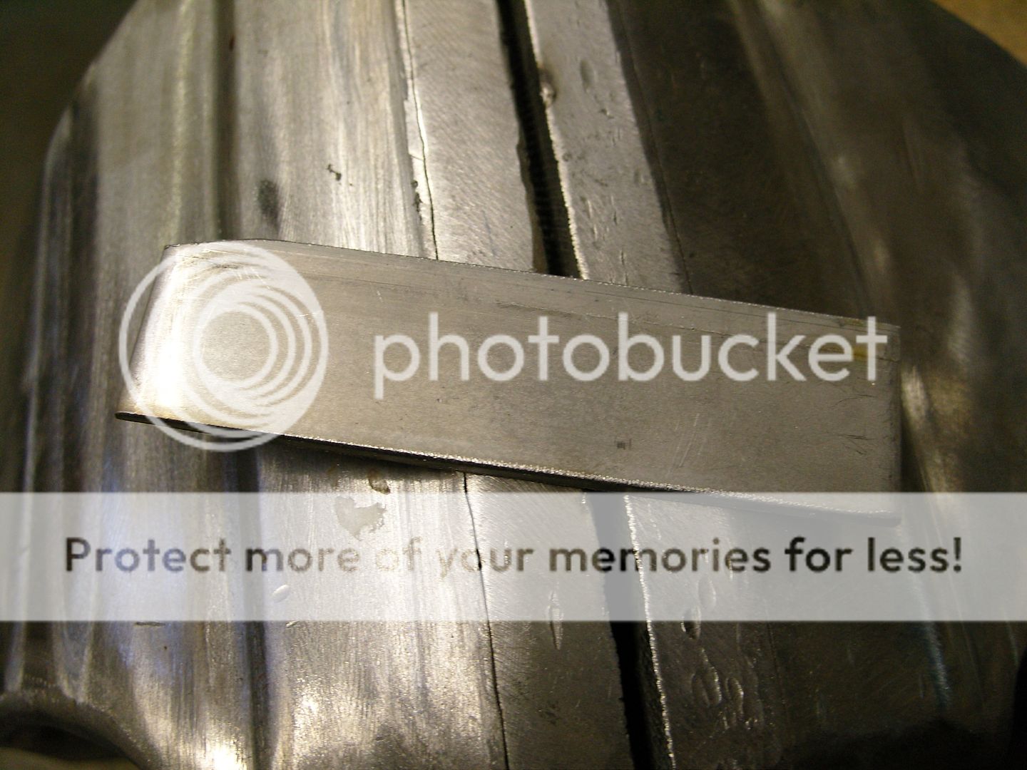
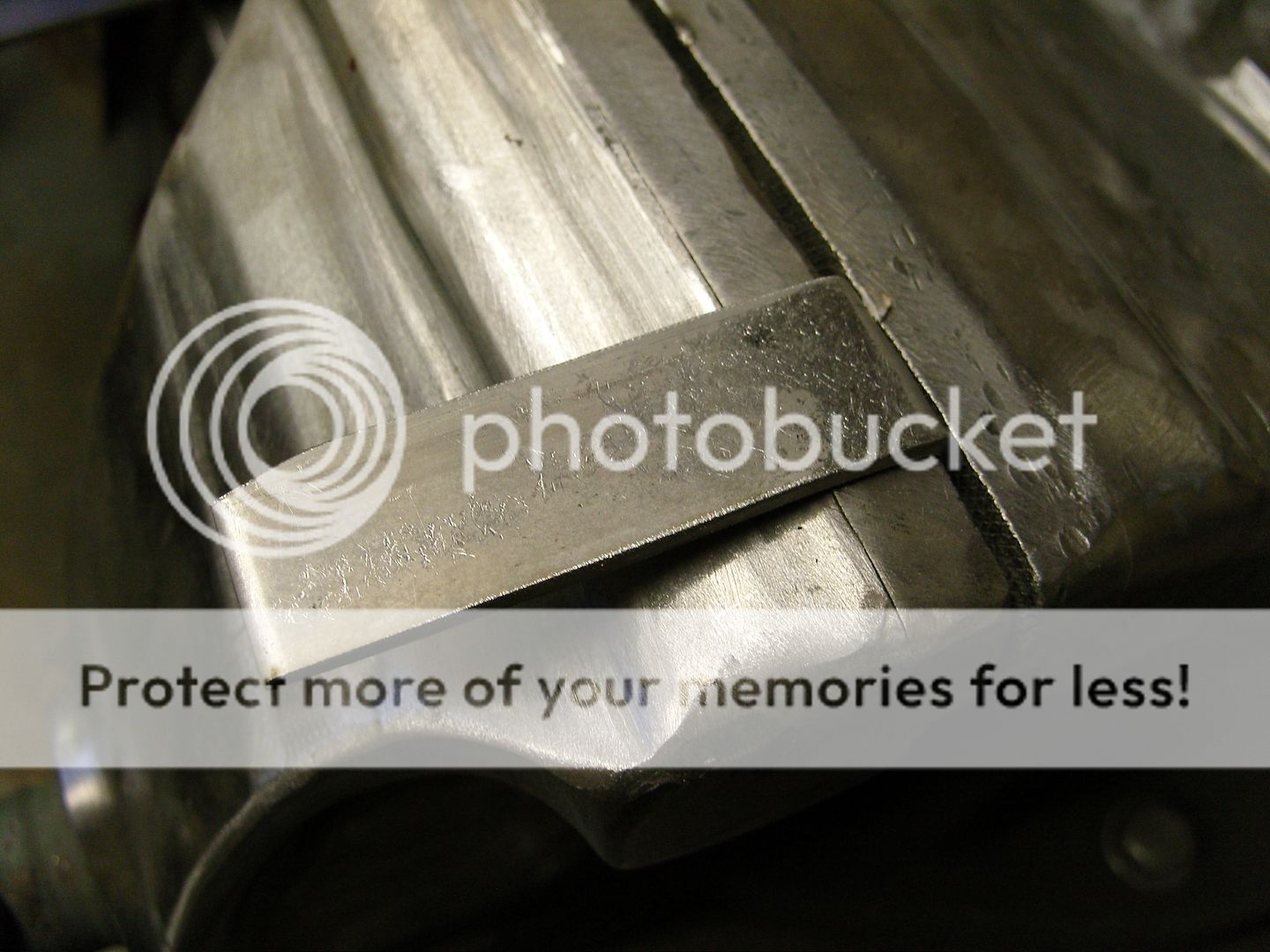
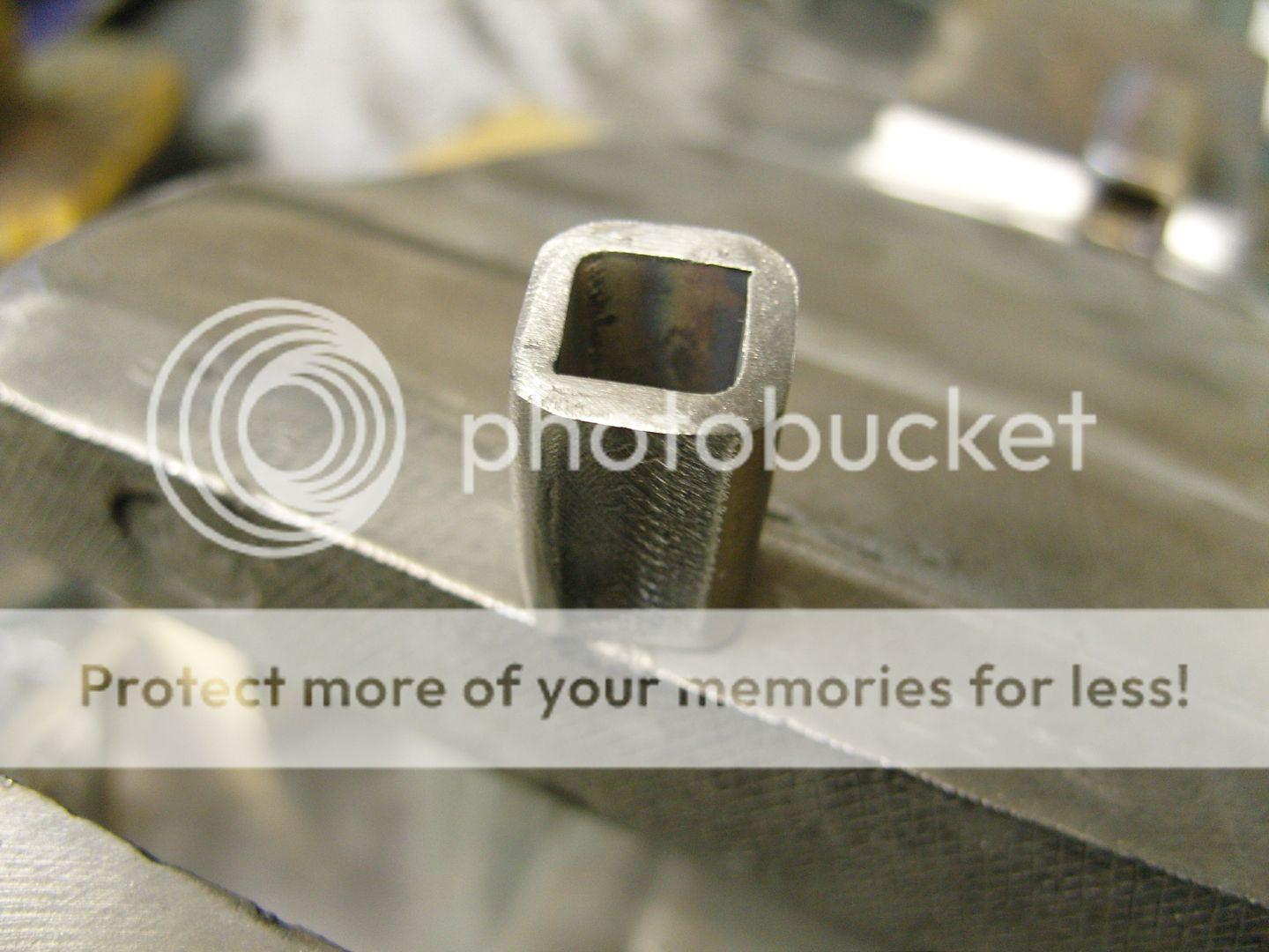
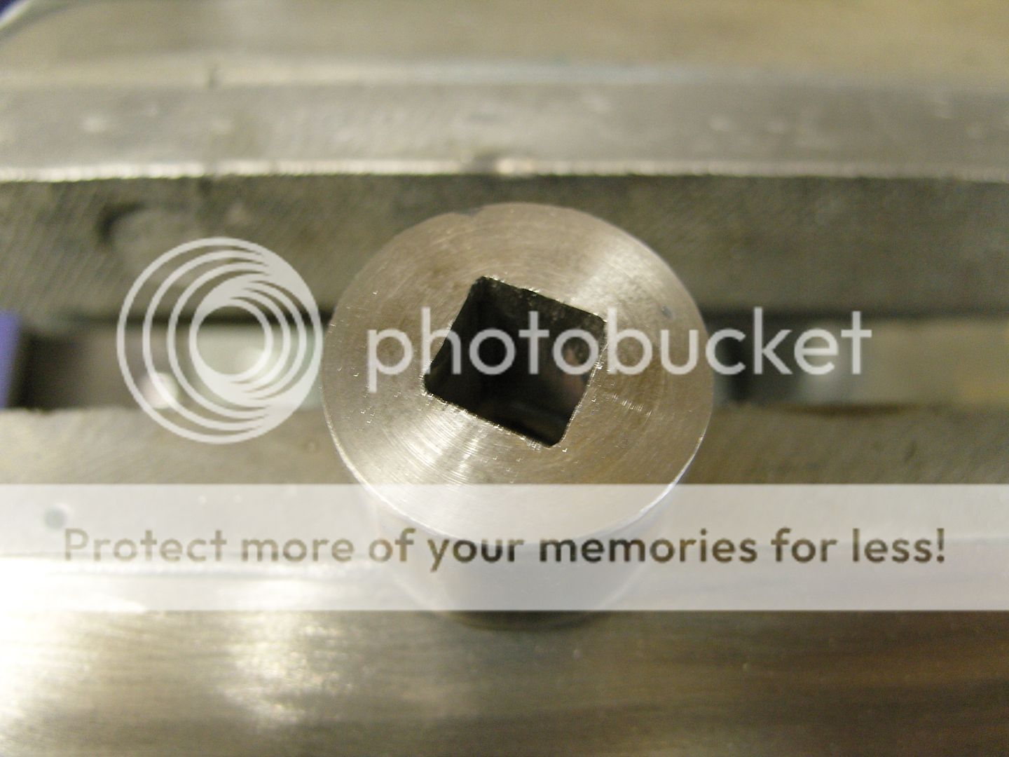
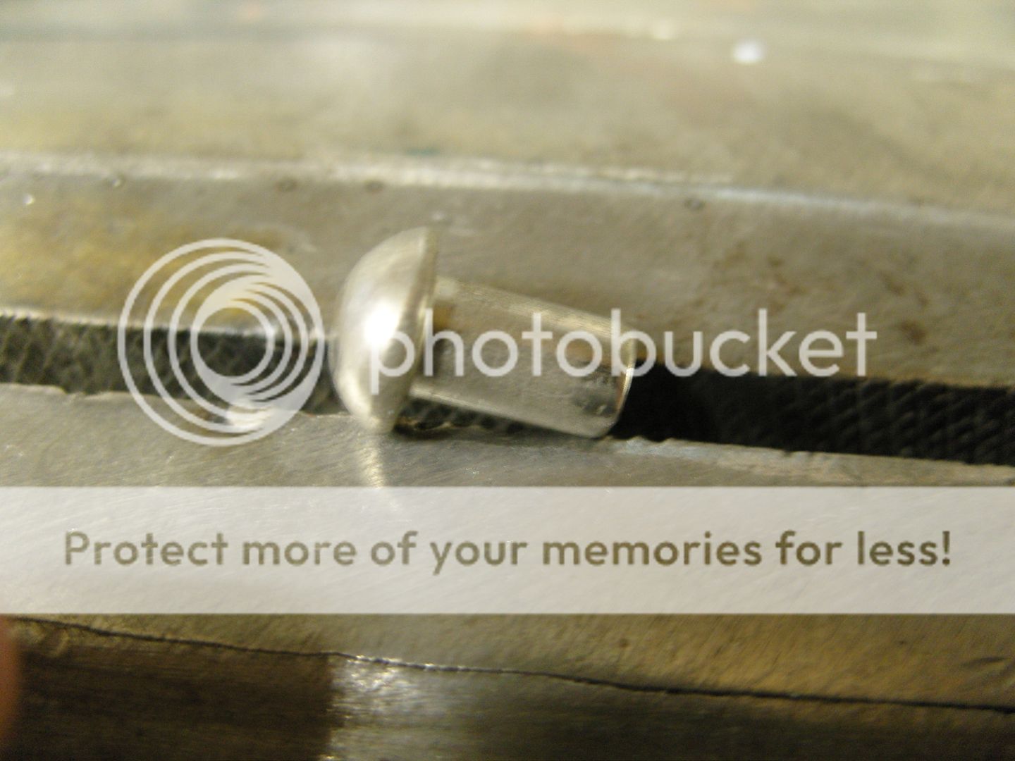
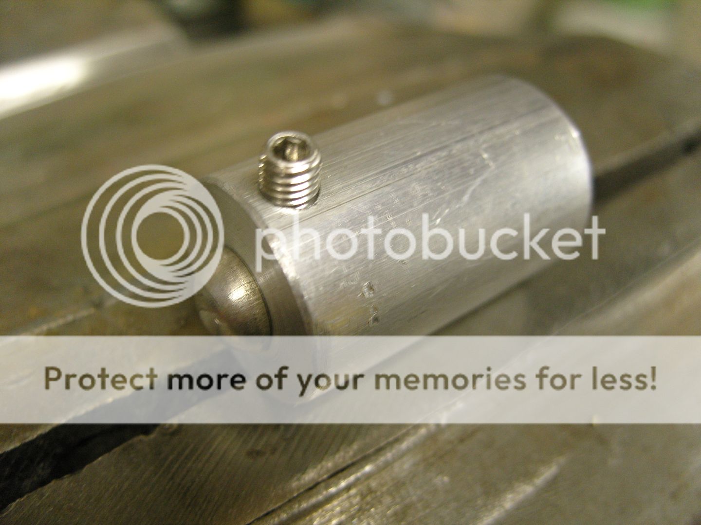
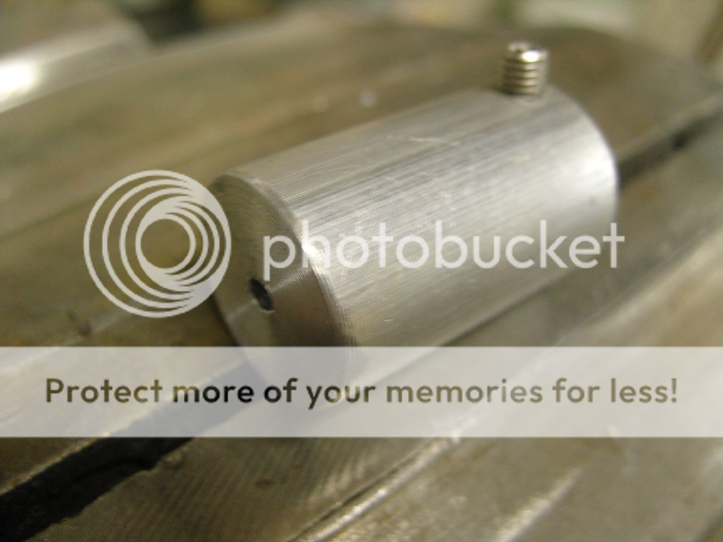
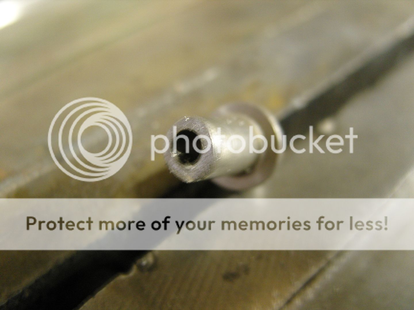
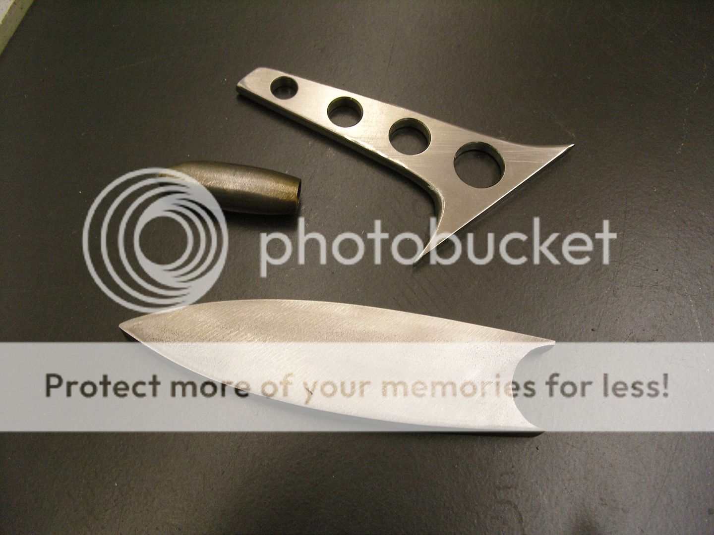
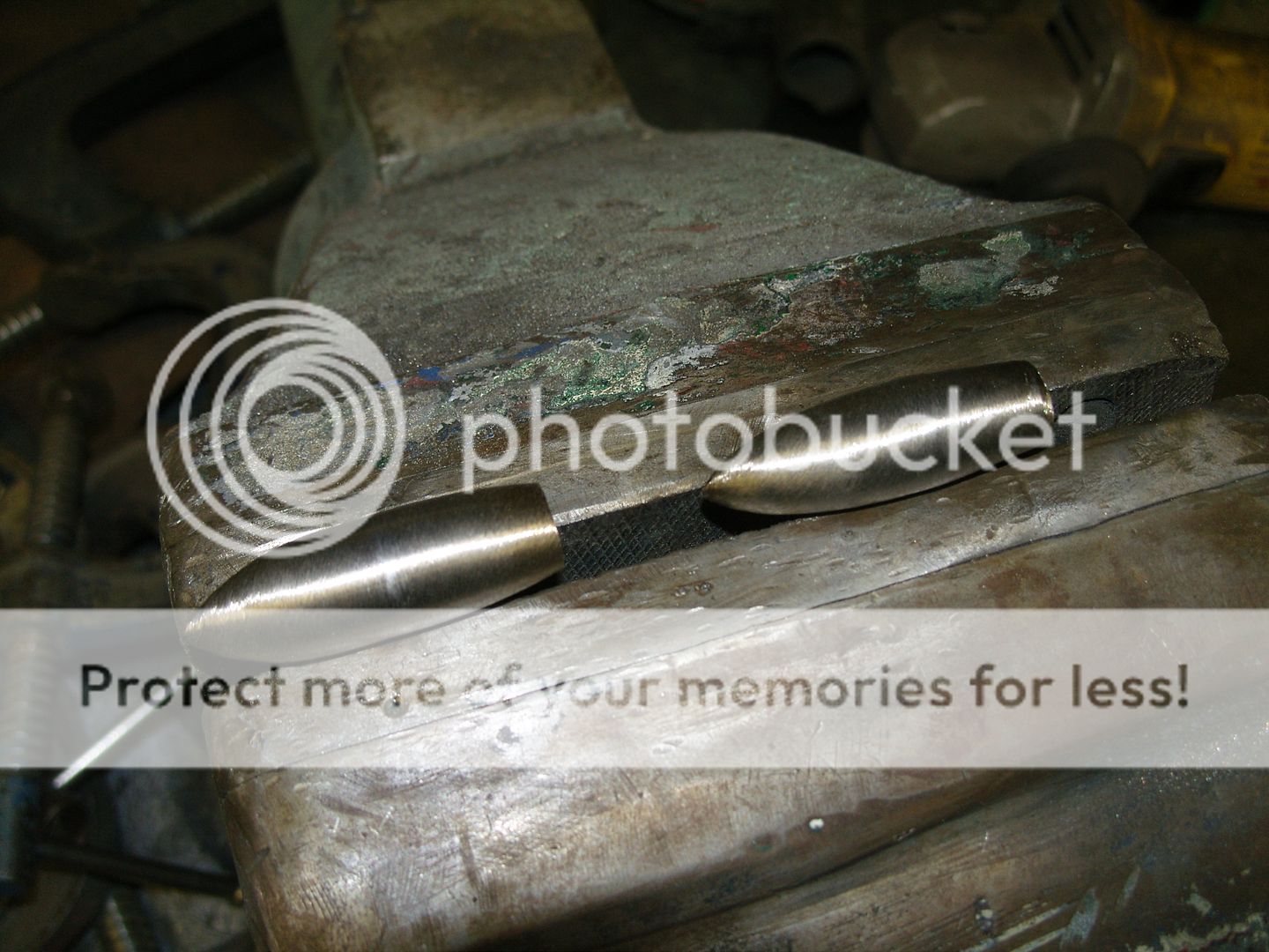
First a piece of 10mm stainless bar was drilled for the tail scallop, then it was cut in half so each half had a semi circle in it.
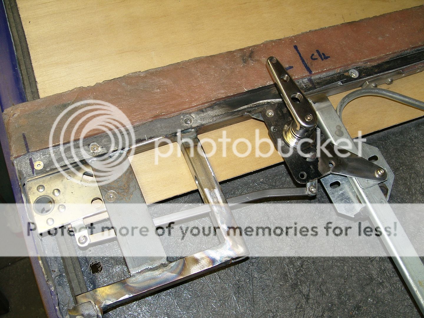
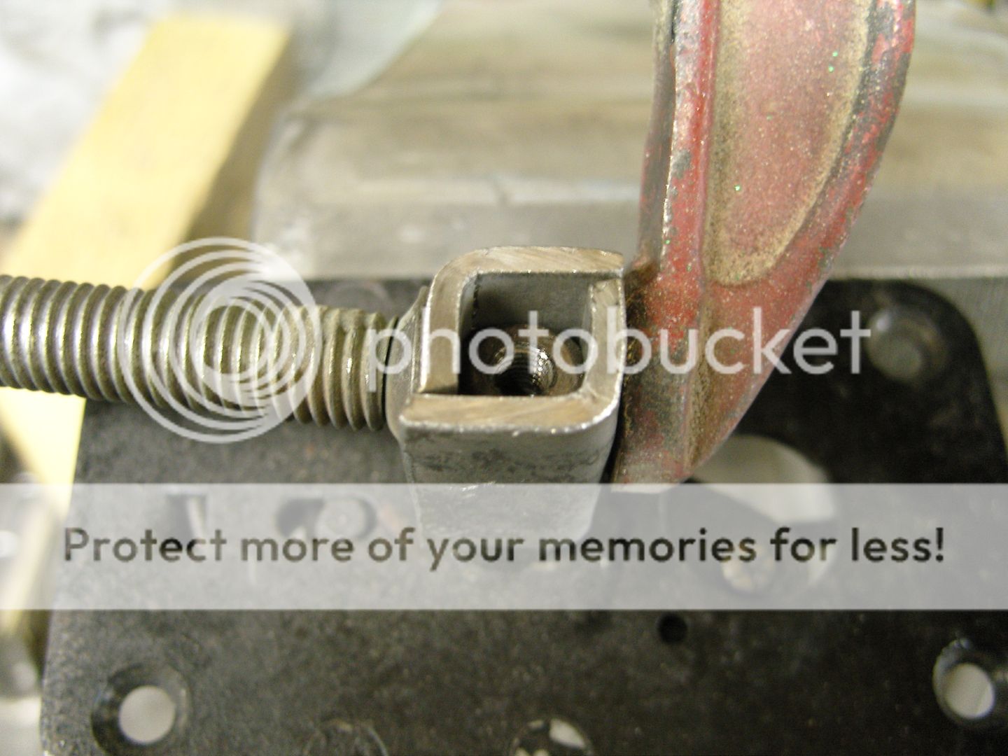
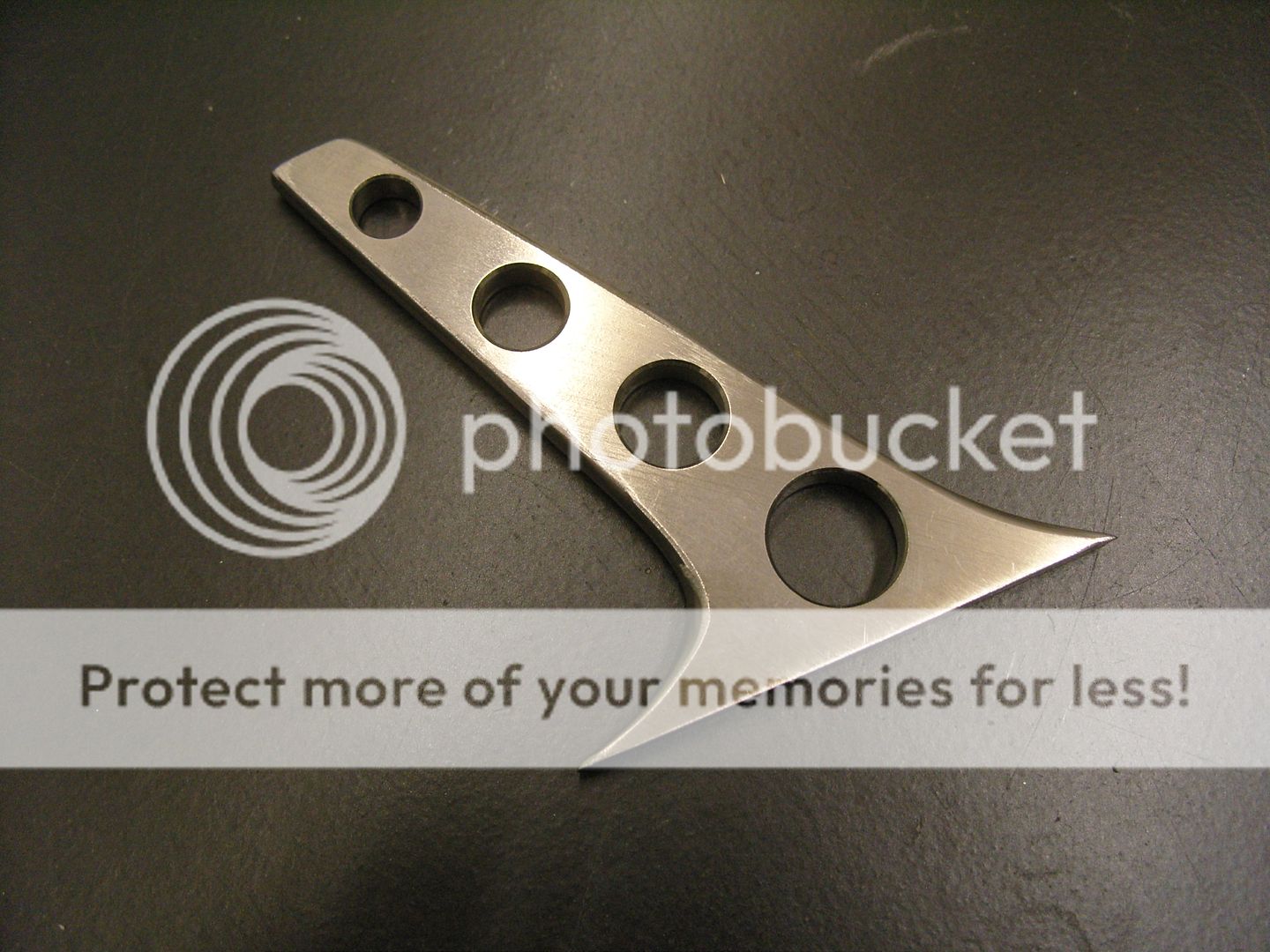
The upright is made from 6mm plate, all stainless is 316L


Mirrors26T2.jpg


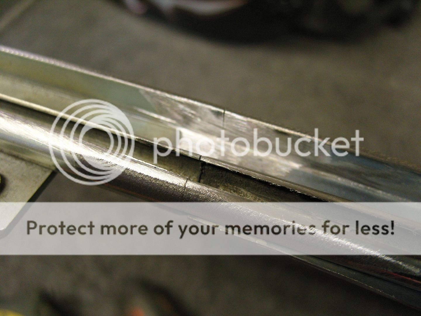
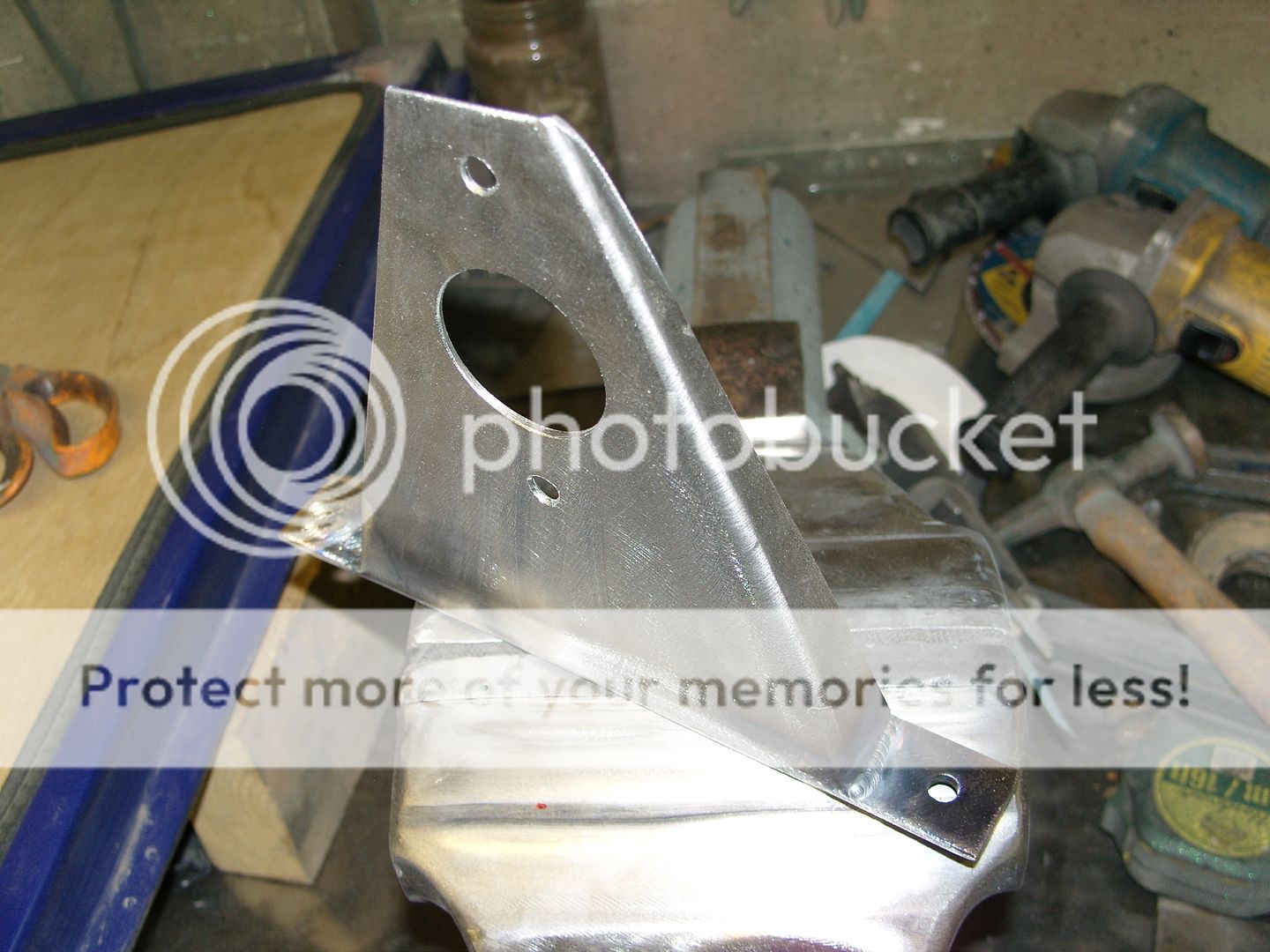
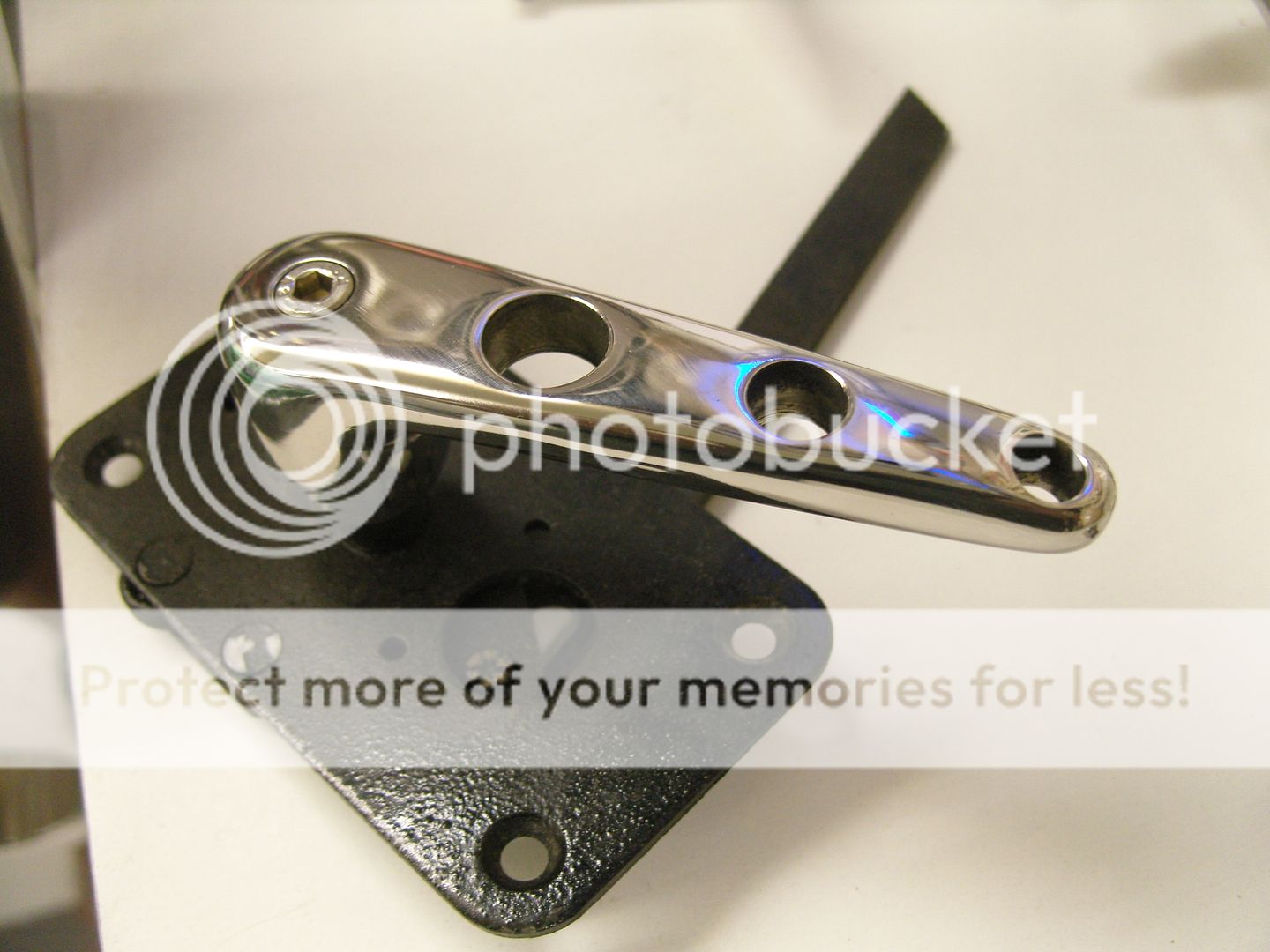
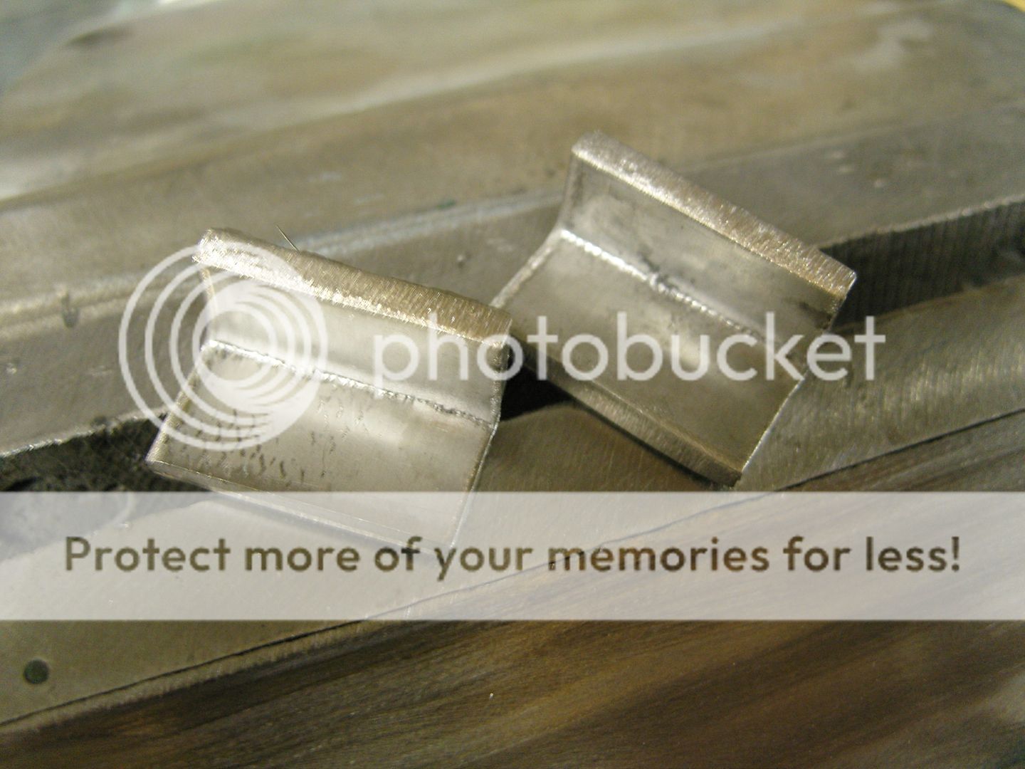
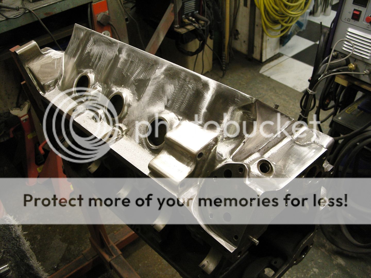
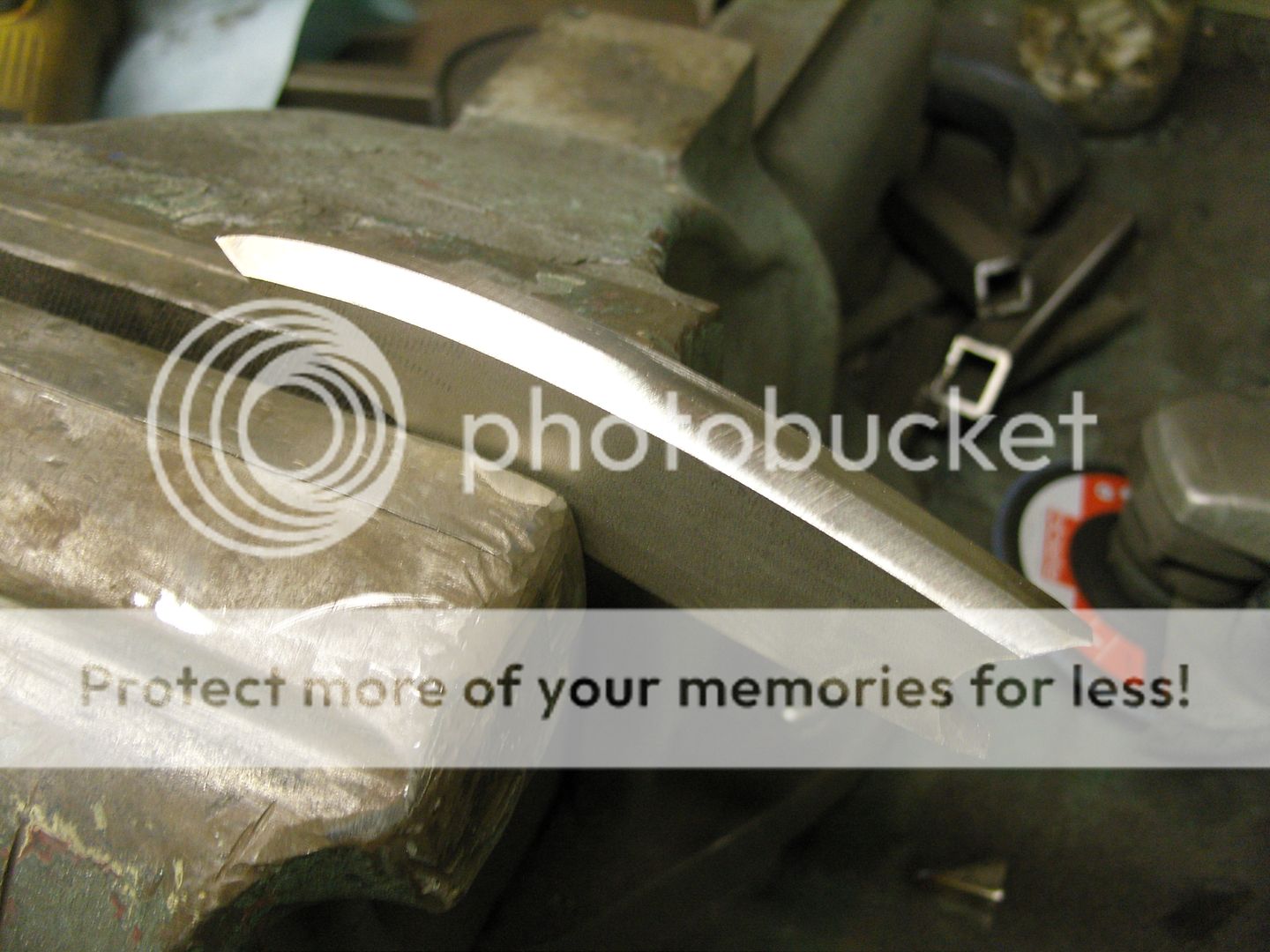
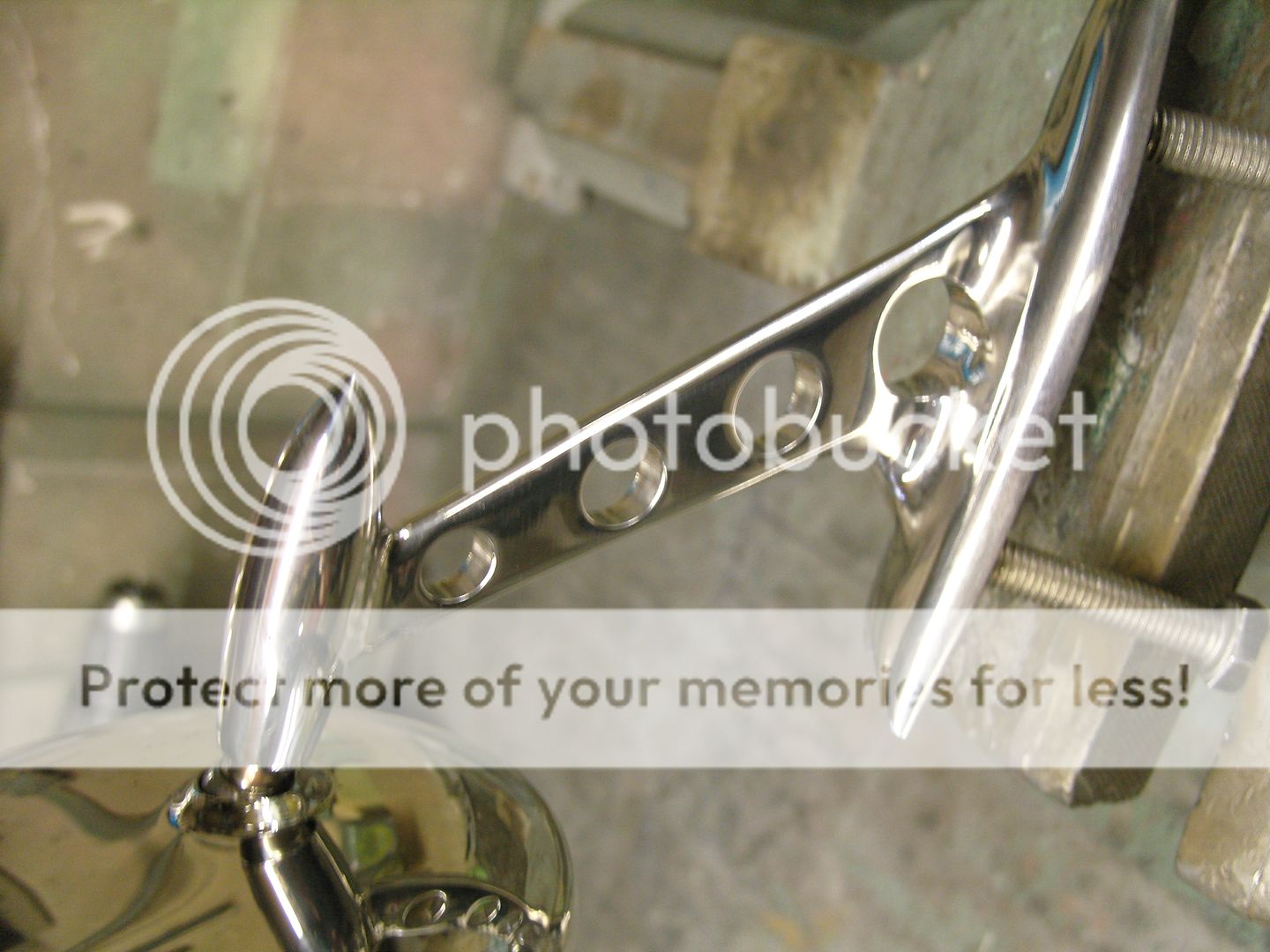
Next the basic shaped was cut and ground with a 1mm cutting disc and a flap disc in a angle grinder. The other parts were cut out, drilled and turned ready for welding together, the parts were polished before welding so only the welds needed blending and fettling.


Mirrors26T7.jpg


Mirrors28july2010.jpg


Mirrors28july20101.jpg


Mirrors26T.jpg


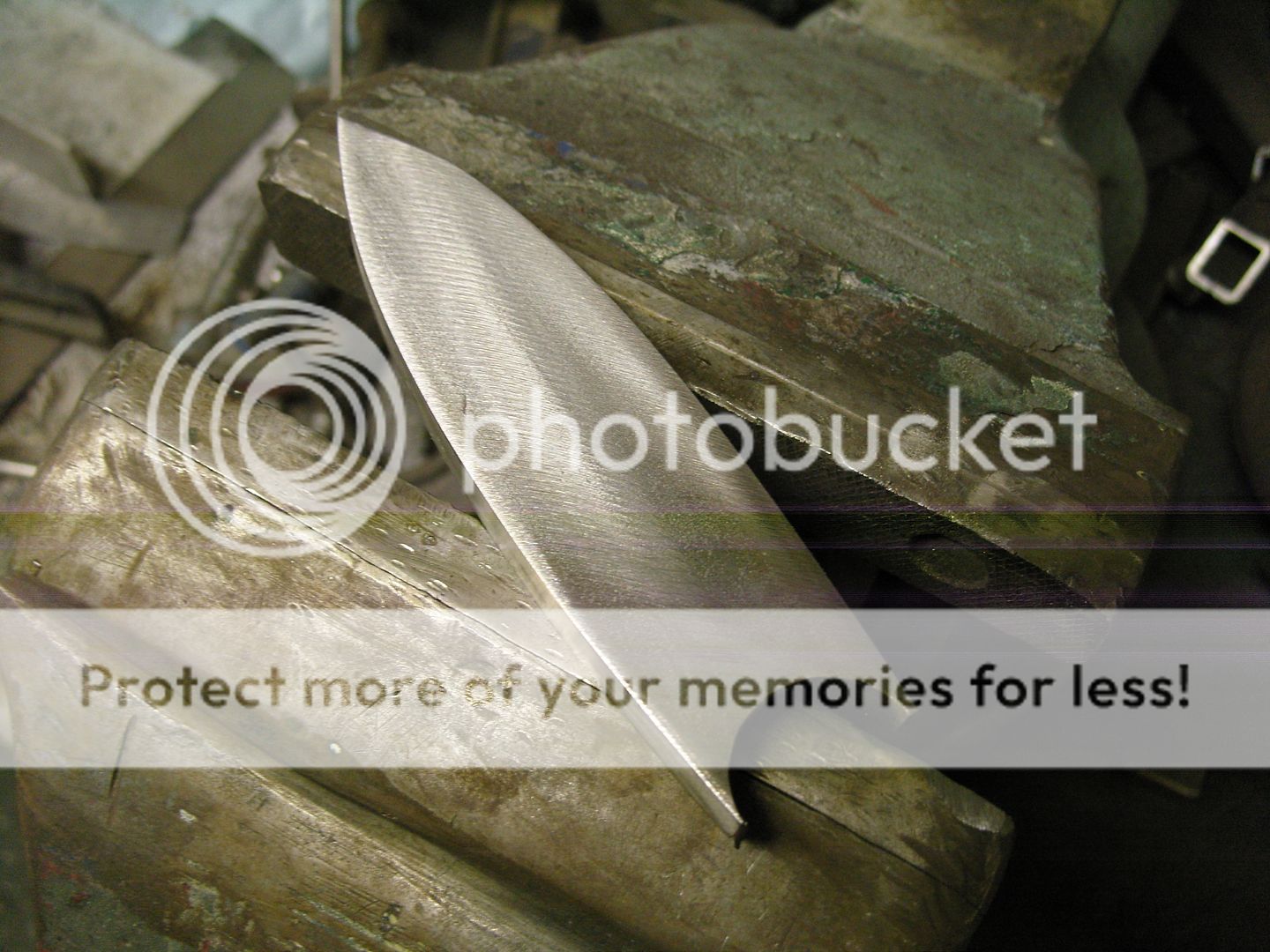
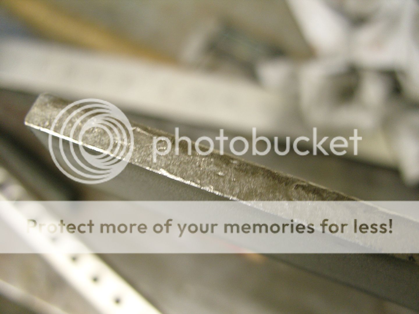
Next the edes were chamfered several times till a 50p shape was acheived, then the edges were soft sanded till smooth and radiused.


Mirrors26T8.jpg


Mirrors26T10.jpg


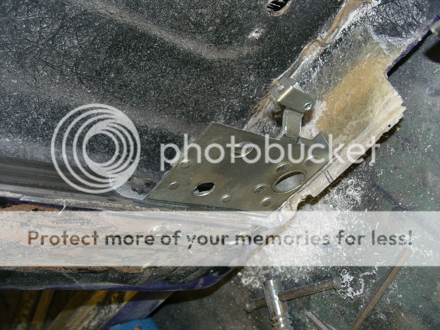
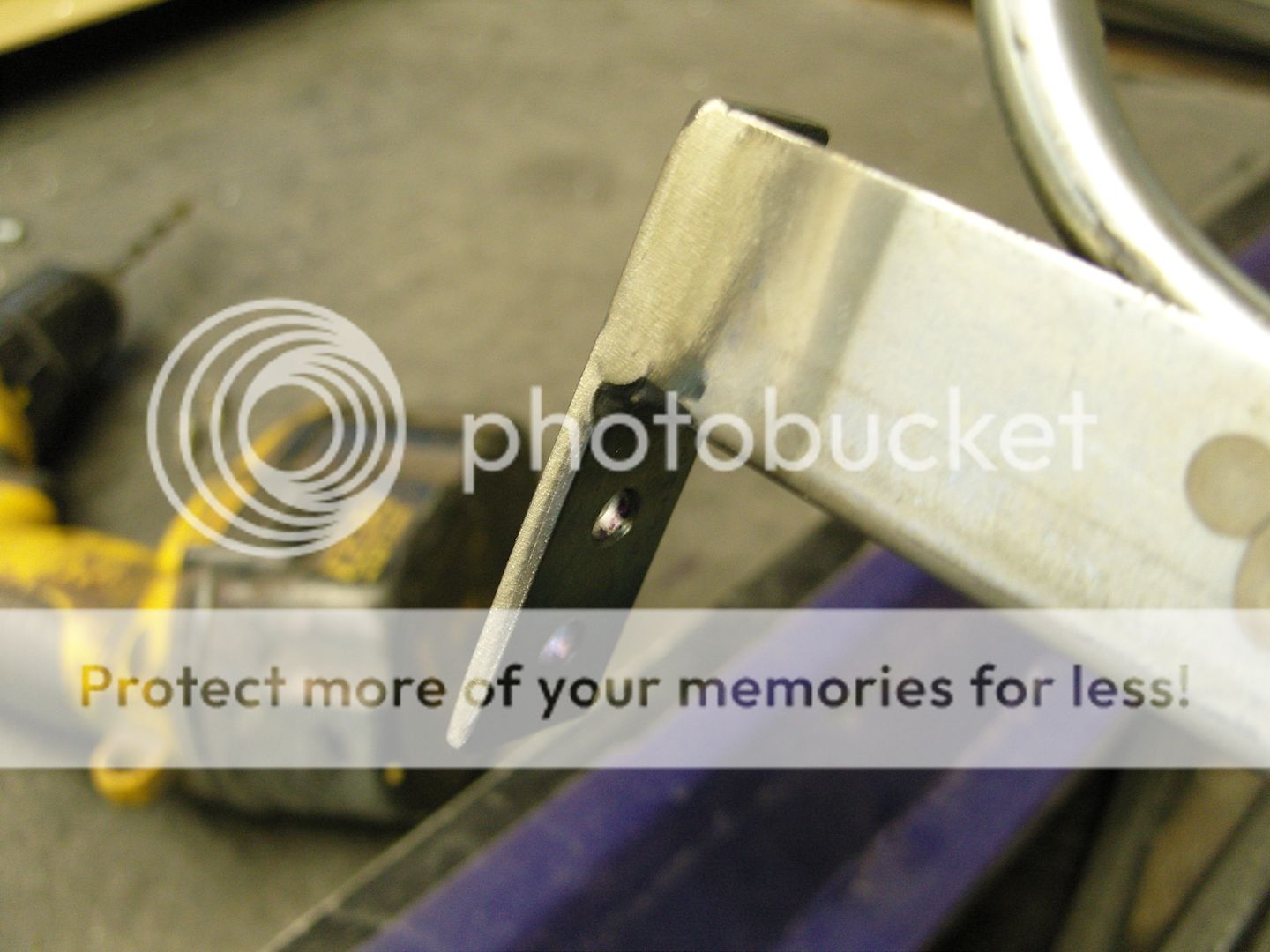
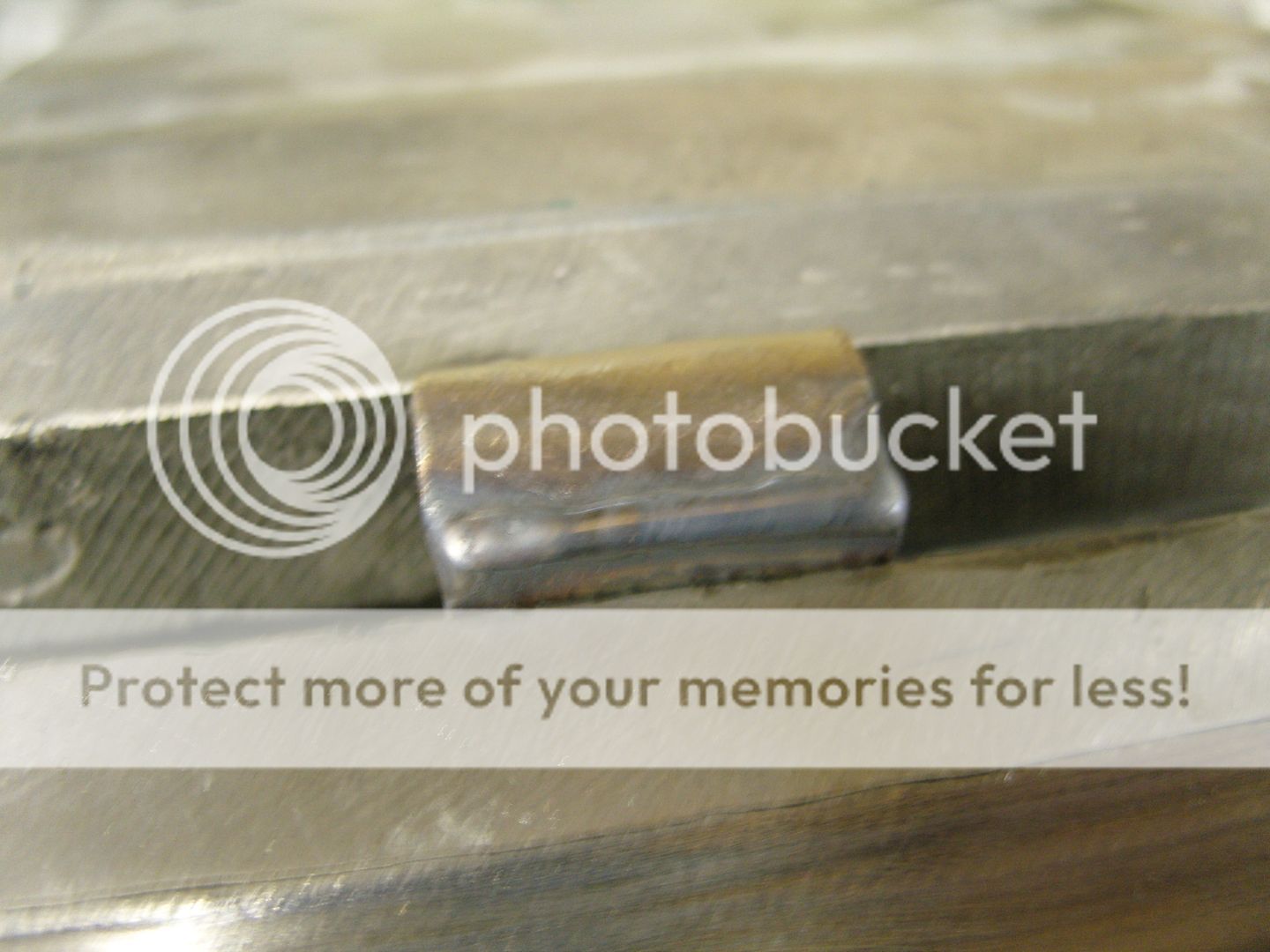
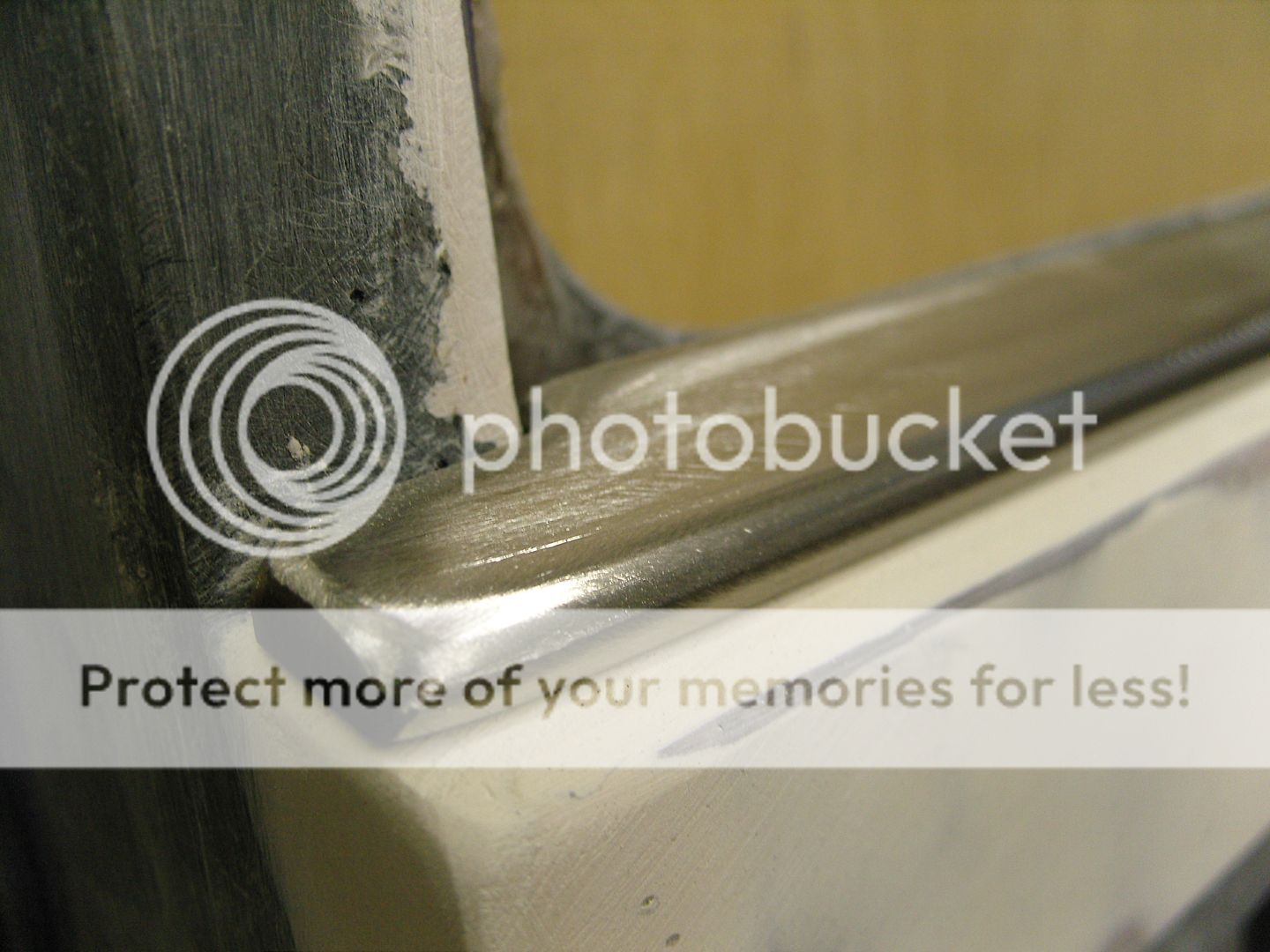
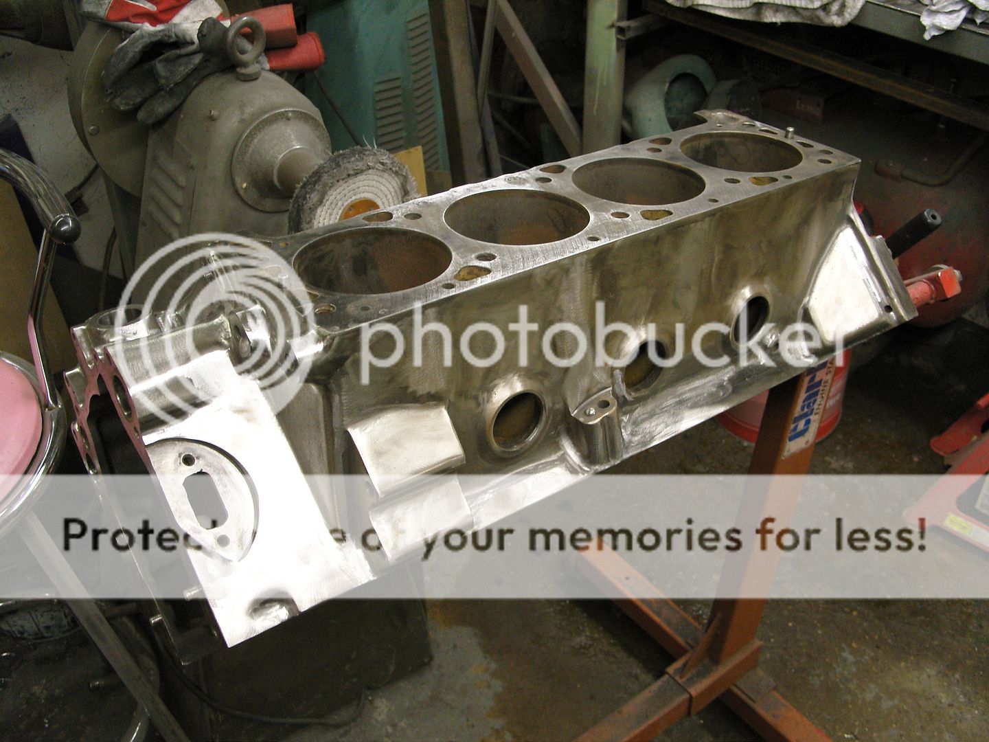
The reverse side had to be hollowed out as this sit on a swage line so again the back was ground away to suit.


Mirrors28july20102.jpg


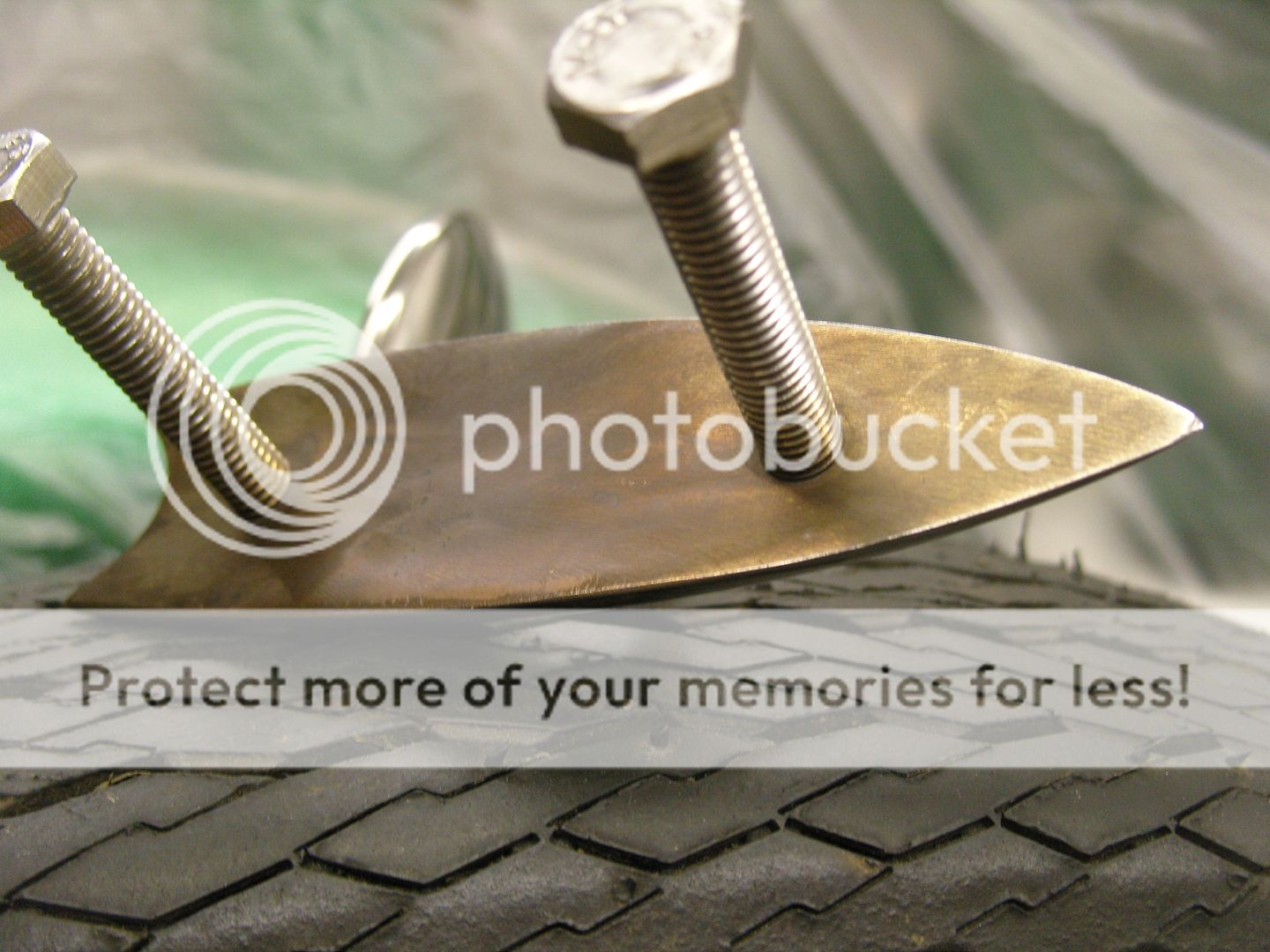
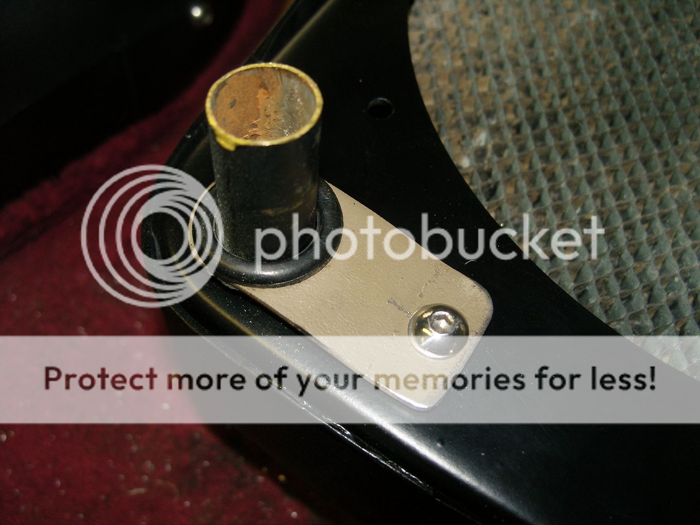
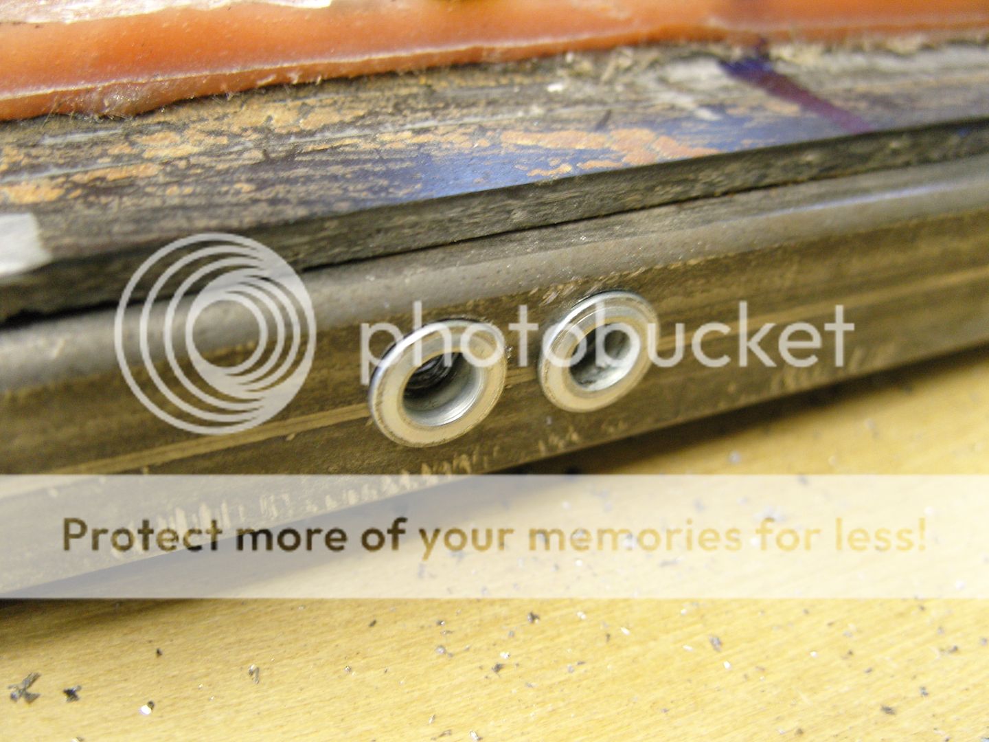
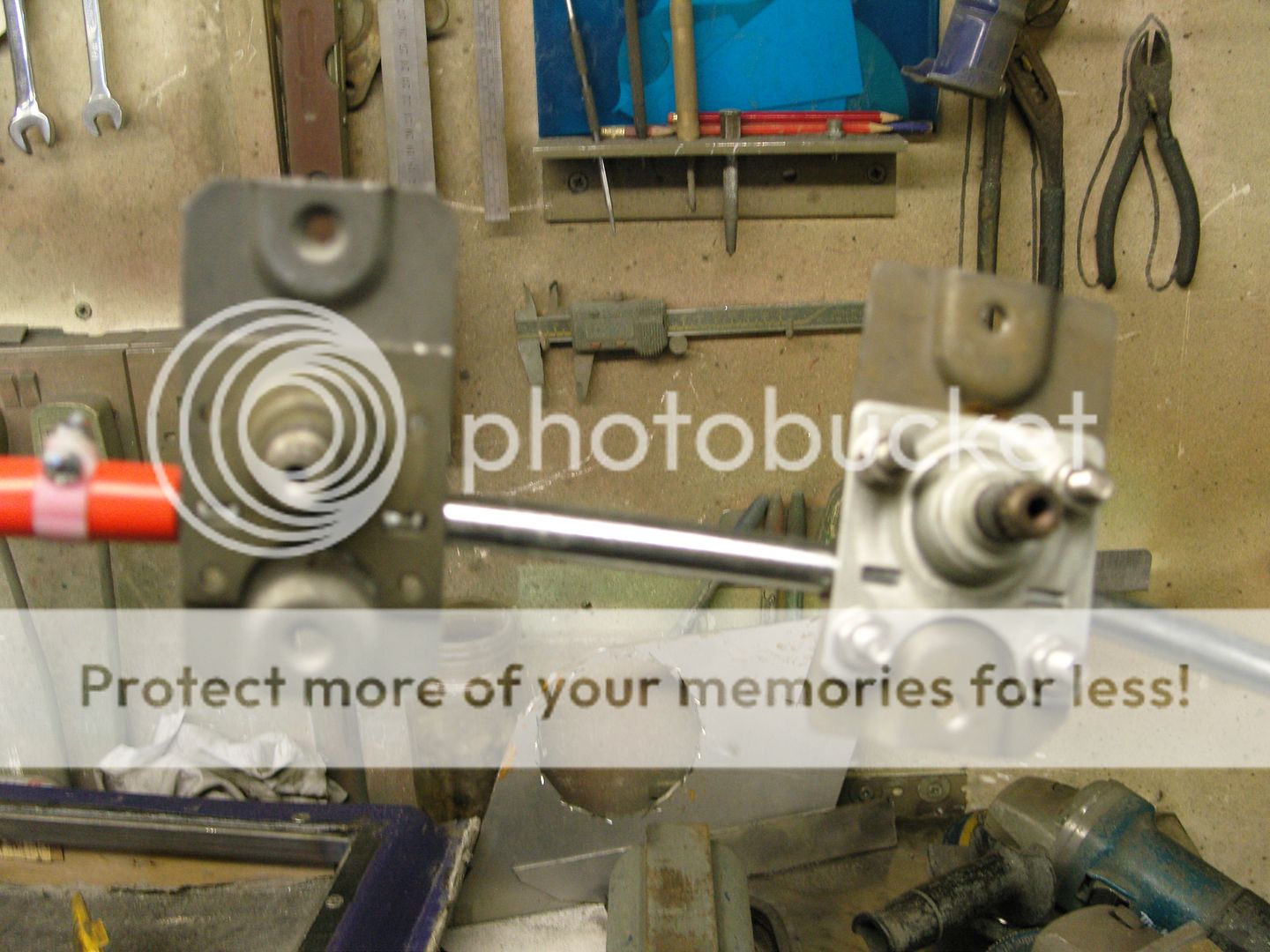
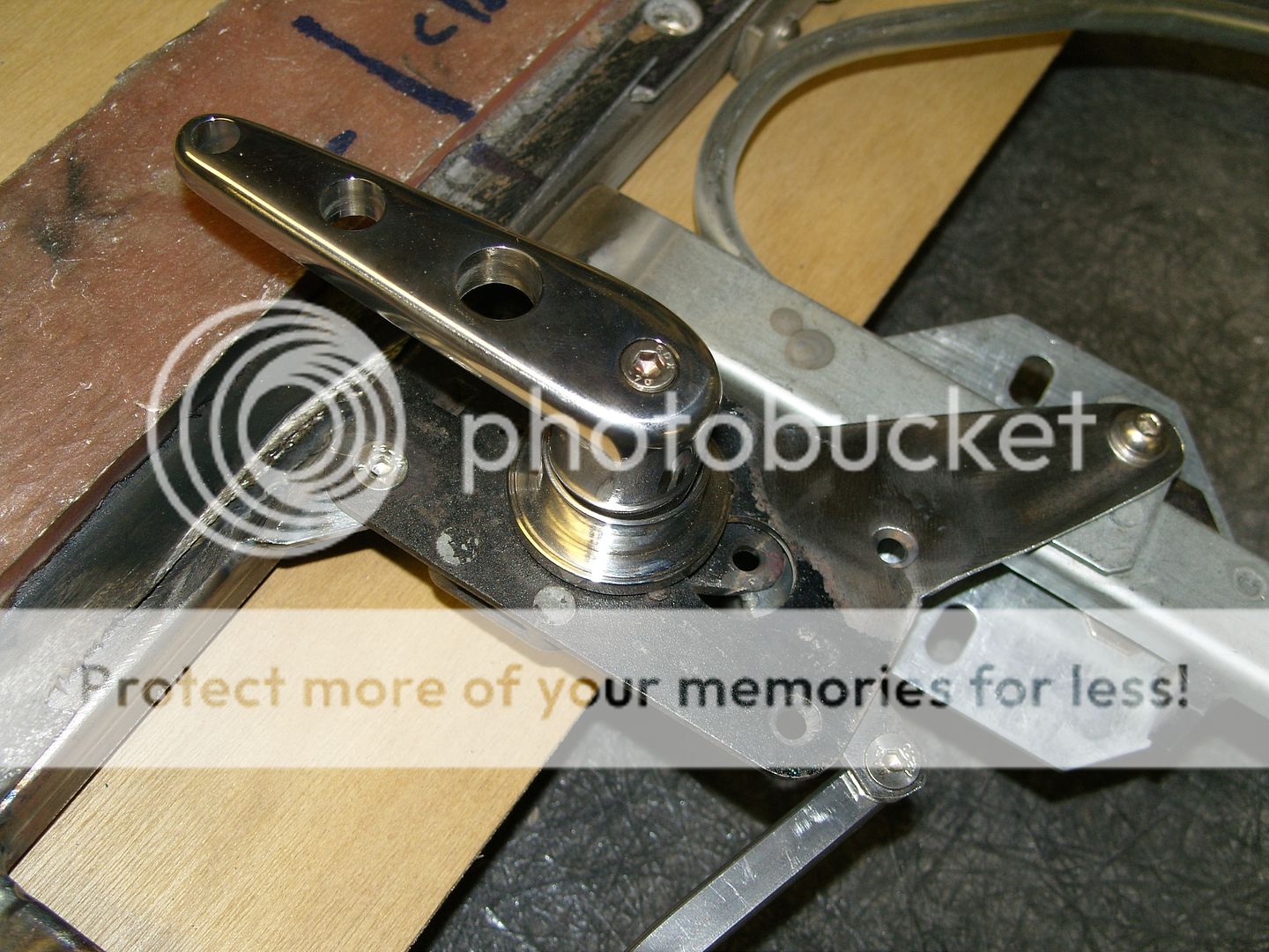
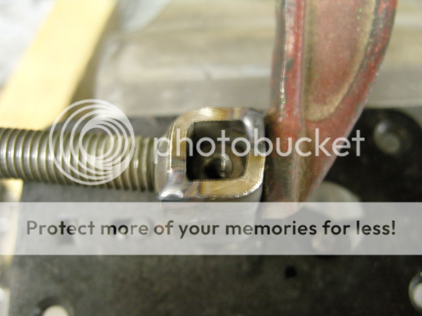
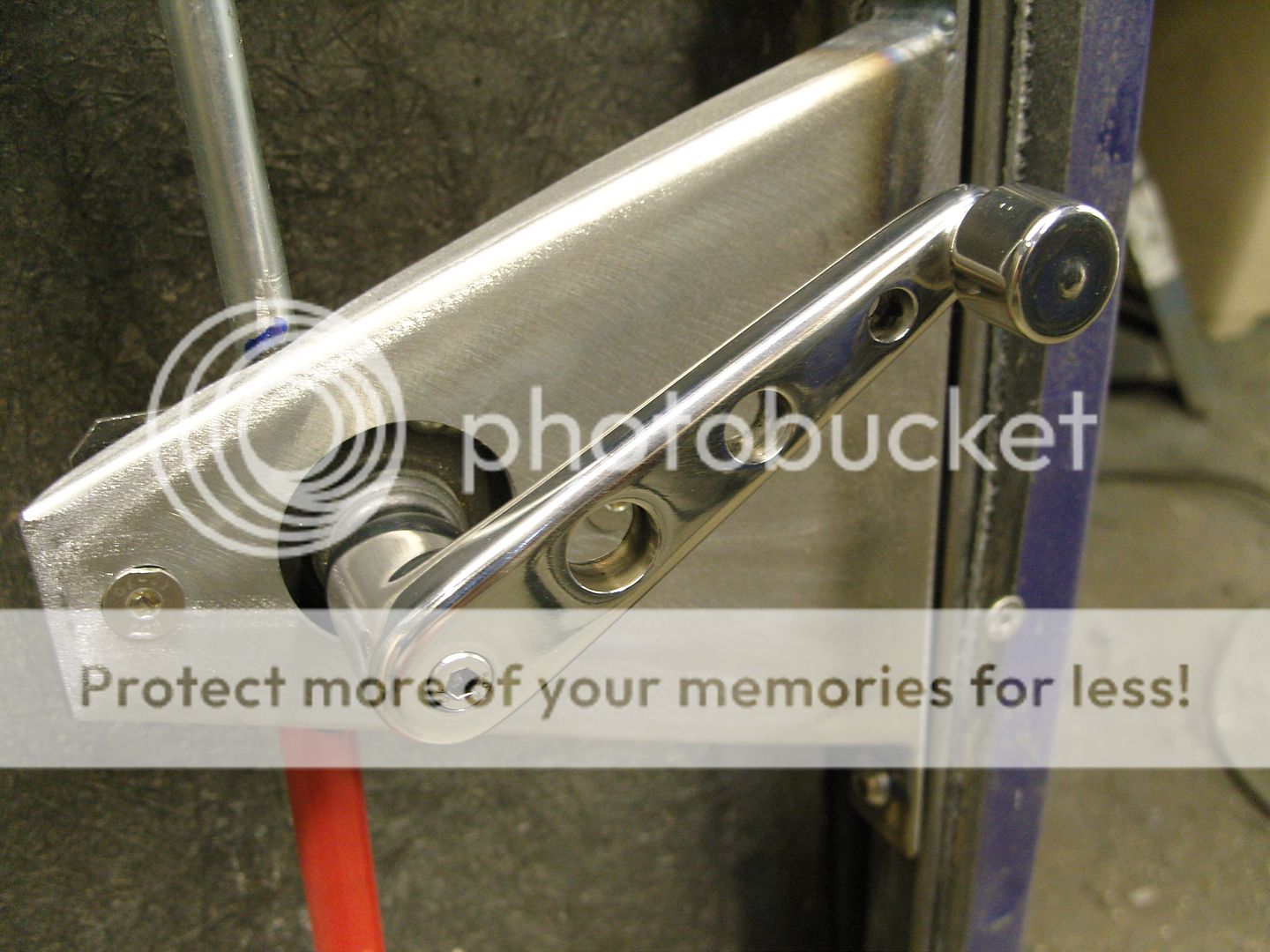
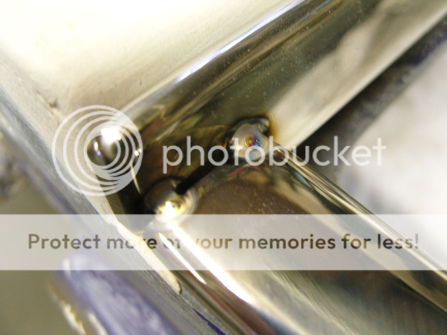
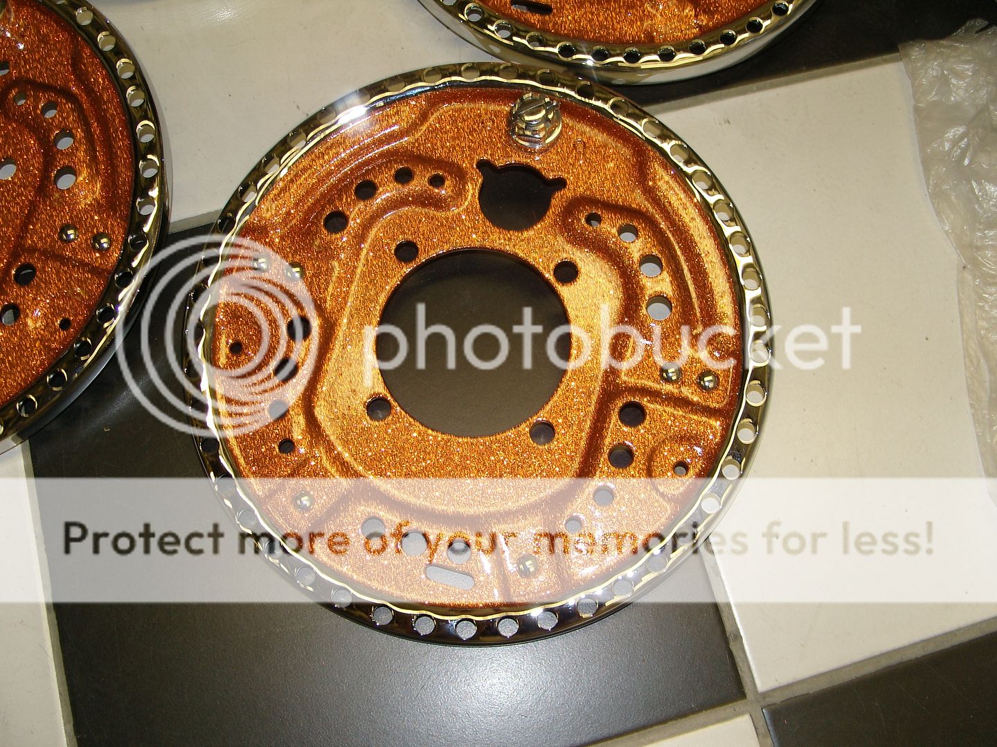
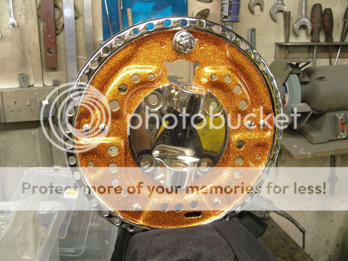
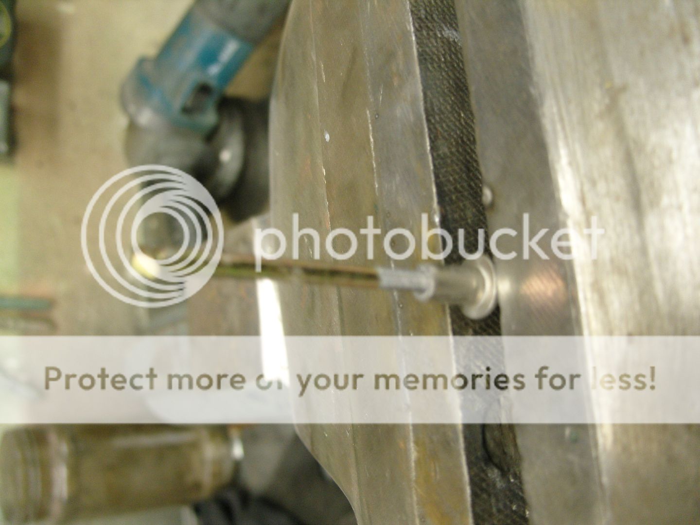
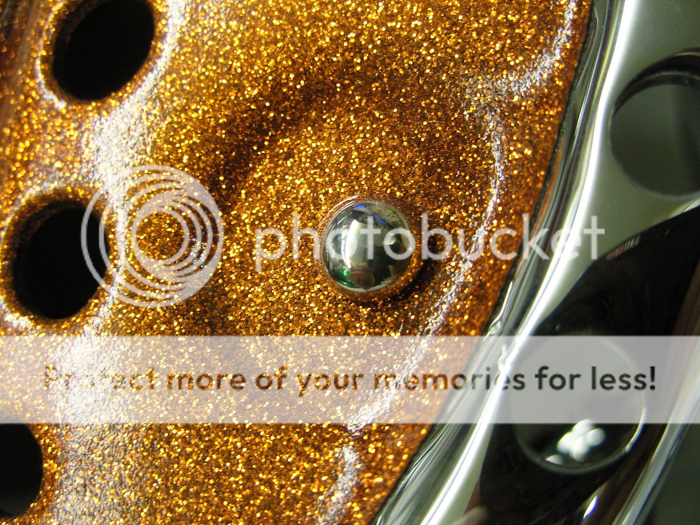
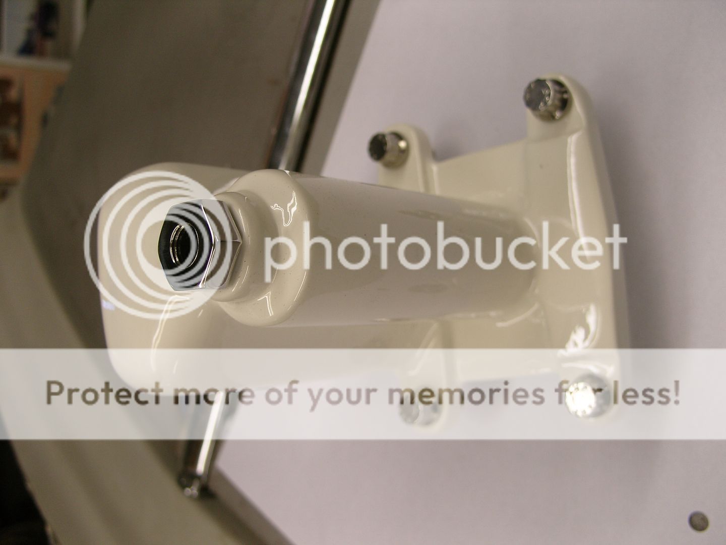
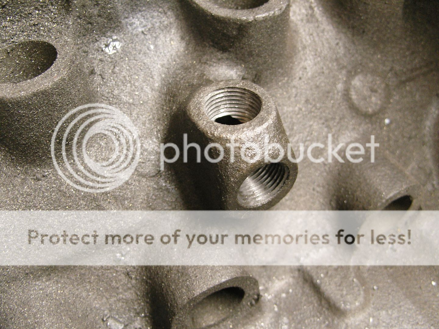
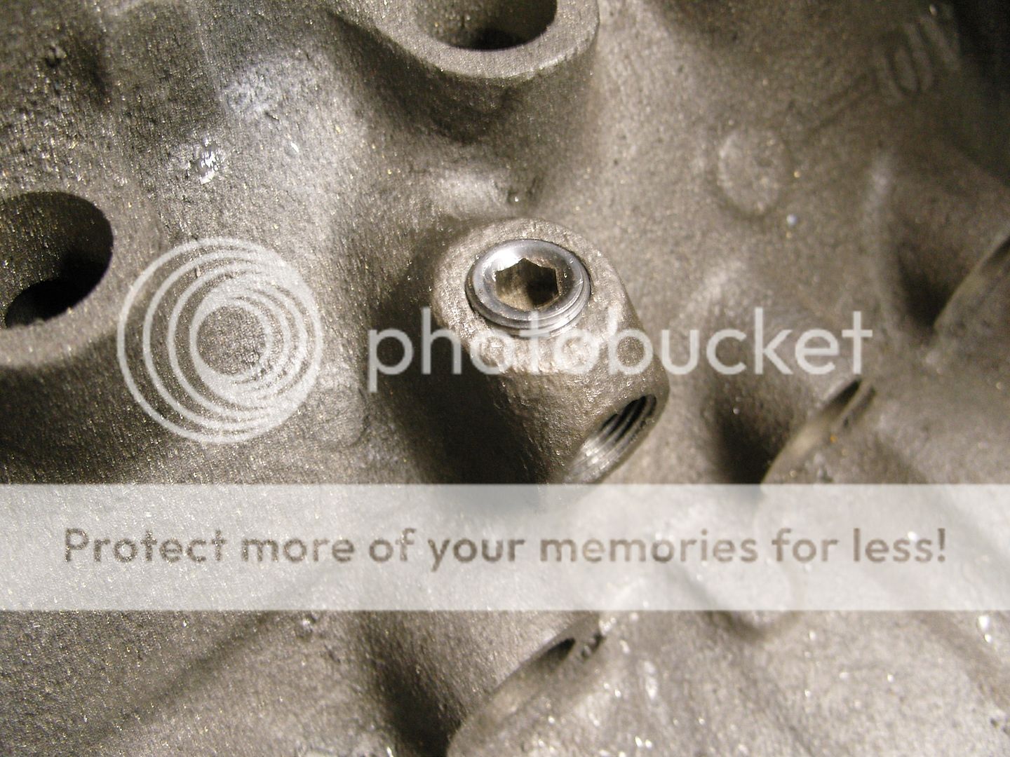
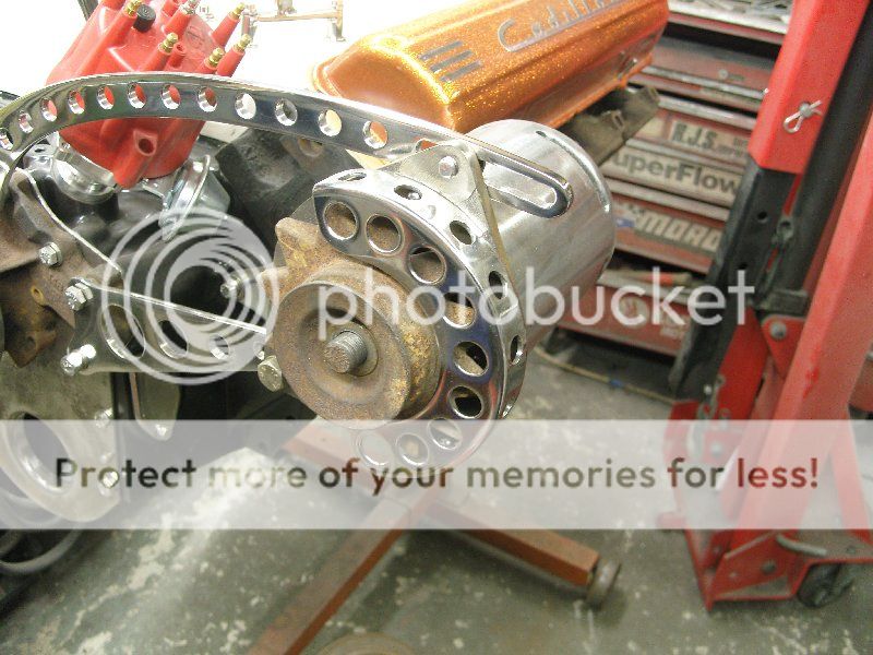
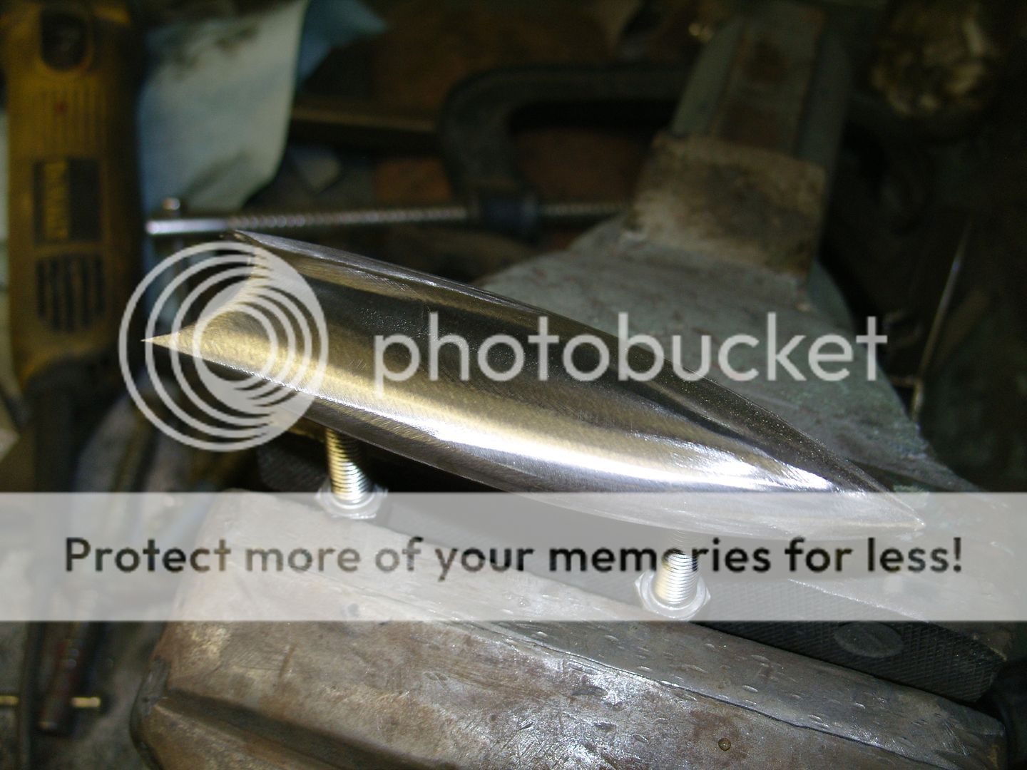
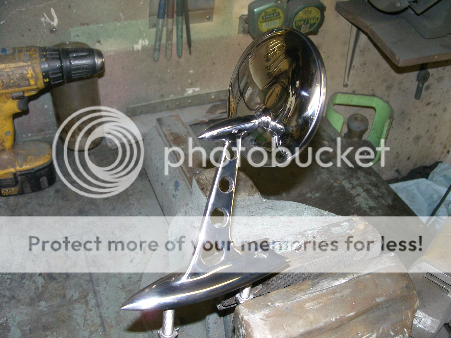
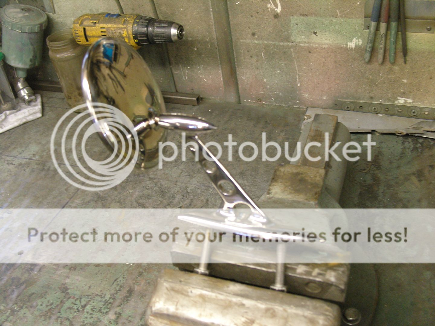
2 x 6.8mm holes were drilled and tapped 8mm for mounting studs, the long bolts are temporary and for holding during the polishing process.
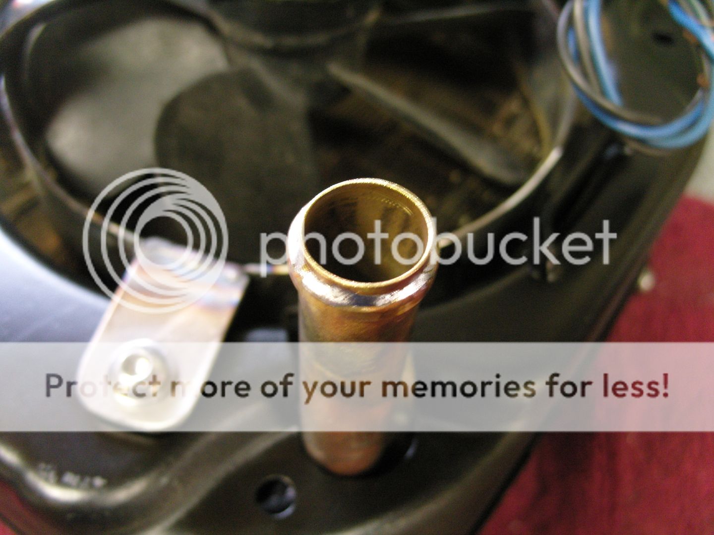
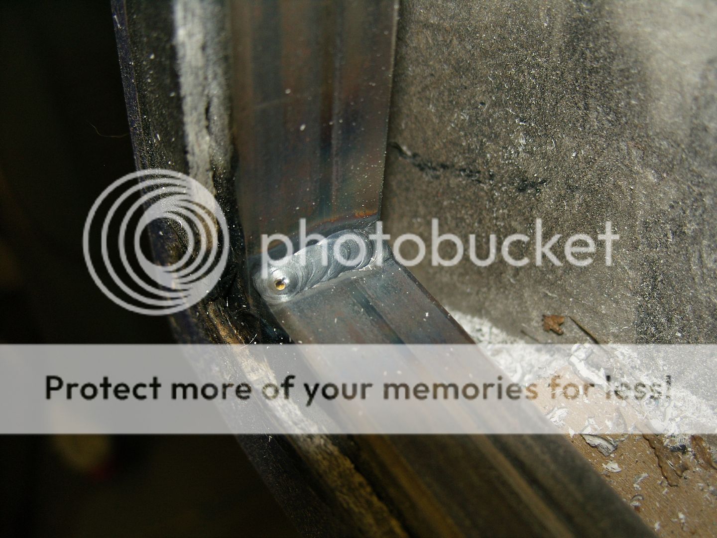
All the parts were then TIG welded together, a fair bit of rod was used so i had something to get a nice radius with.

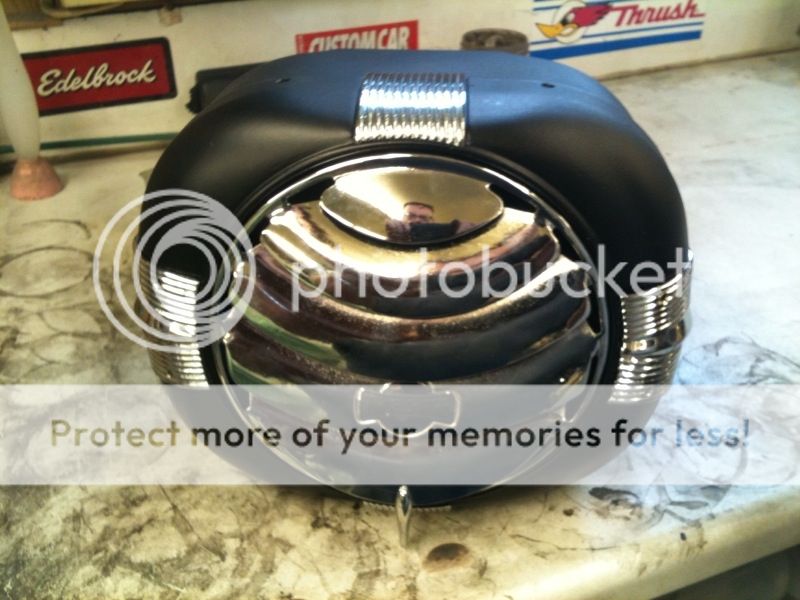
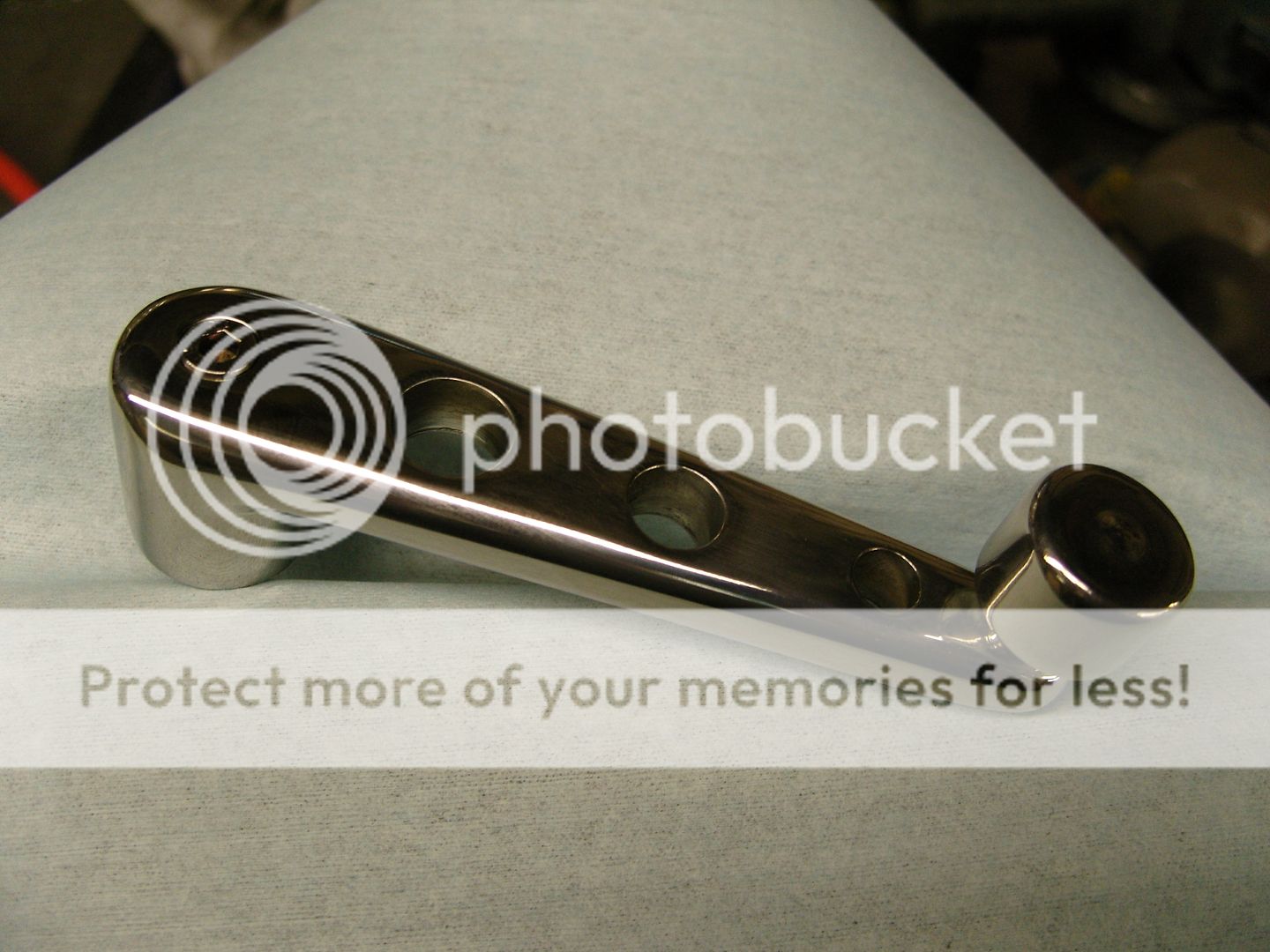
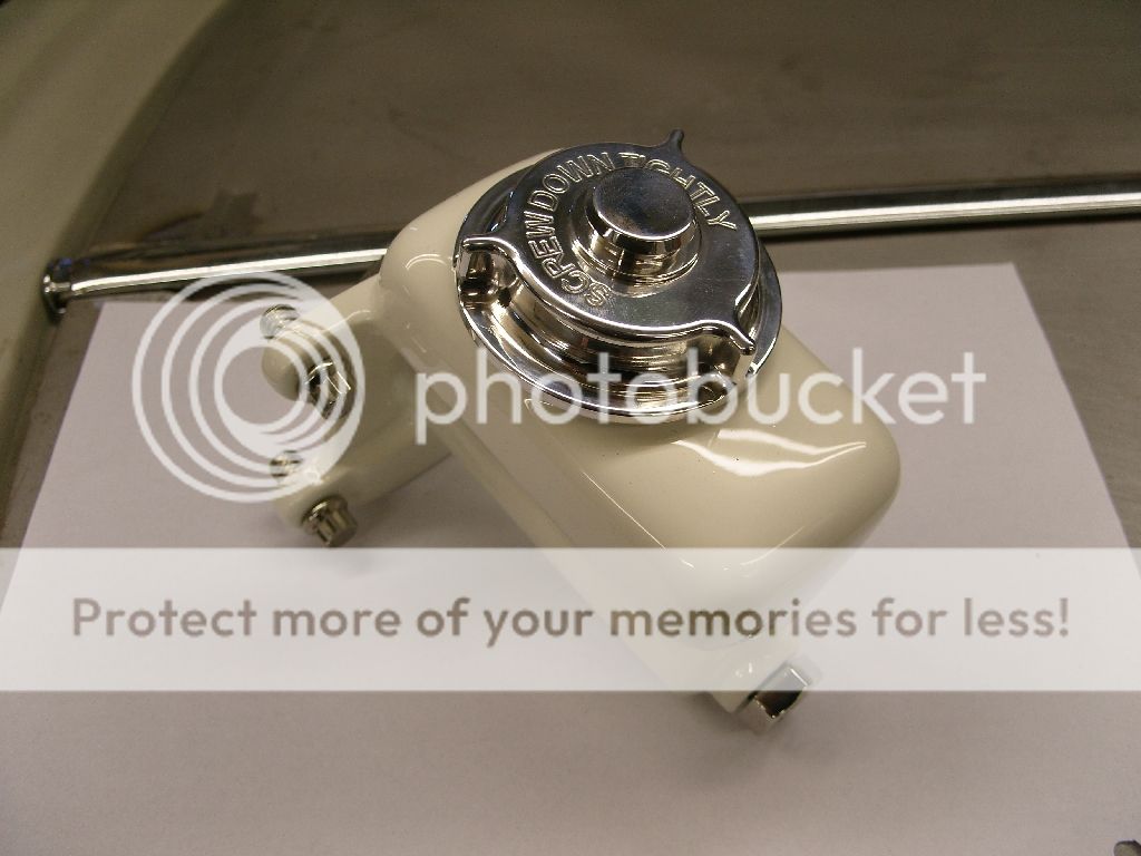
The finished Mirrors.


Mirrors26T14.jpg


Mirrors26T16.jpg


Mirrors26T18.jpg


________________
 
Hi Gerry, when i was posting it i thought this is a coupe so may not be doing the right thing. Originally this was going to have a bucket body so matbe that will make it acceptable ???


Hi Steve.
Welcome. I hope the guys will appreciate your work as much as I do. I know its not a bucket but come on theres so much to learn here. I cant wait to line up the Fad and the coupe together at the Nats one day. Steve post some pics of your bucket as well please.
Gerry
 
It didn't take long Gerry as it is a copy & paste job, The project is a lot further than it looks, more up later. Buzz me about TH350 slip joint, I have new one's.

Thanks to the other guys that commented, Its appreciated

Cheers
Steve.


Steve.
Though the guys would like it. Had no idea you would post the whole lot in one go, but thanks. Oh by the way Im looking for a slip yoke for my 350.
Gerry
 
Finally decided what to do with the brake backplates so i polished the outside rim and got my mate to chrome them, I will flake the centre bit, I think it will look better than a mass of chrome and give a bit of contrast.

Chromebackplates1august2010.jpg


Chromebackplates1august20104-1.jpg


The other night i had a few hours spare so decided to pull the Tropic Aire heater apart that i had picked up at a swap in the states. First job was to take it apart for modifying and then off for media blasting.


TropicAireHeater2-1.jpg


TropicAireHeater4-1.jpg


These things had massive fan motors in them so i chopped off the motor mount as i will be using a 6" fan/motor from a Gileera motorbike thats nice and slim and will reduce the heater thickness by half. I polished various bits and sent them to my mate for chroming.


TropicAireHeater6-1.jpg


The body after blasting was primed with 2 coats of black epoxy primer and will be painted flake later with various other small bits. tabs were made up to held the motor assembly and the long tubes on the matrix cut down to a shorter length. removing the rear section also removed the support that held the matrix tubes so 2 small tabs were made and fitted with a grommet to support the tubes and were bolted to the heater body.
Chopping the tubes down meant losing the small beaded ends which stop the hose from blowing off so as i couldn't find my small beader roller i spun up a couple of brass rings on the lathe and soldered them in place.


TropicAireHeater11-1.jpg


TropicAireHeater19-1.jpg


photo1.jpg


TropicAireHeater8-1.jpg


__________________
 
Seeing as i hate installing window mechanisms i thought i would get this job out of the way early on

The doors came with a crude Mini based system that didn't work that well to be honest and the window didn't go full travel due to the height of a tall T window.
I thought i might be able too reuse the runners but once i got into the door itself i realised they wern't great either so the door was stripped out, while there i removed the complete inner bottom as it looked like somebody had chewed it out

On inspection the doors wern't as accurate as i thought This isn't a dig at the mould maker as he probably hadn't a decent body to start with but nothing was really very square and there are dips and wobbles on virtually every surface

the easy way out would of been with an electric kit but I did not want electric windows as i feel its more old car with windups and i like them

Here's the door stripped out but still with the window runners in, The runners came out easily as they had been glued in with Gripfill but i then spent ages sanding out the Gripfill with a finger sander


TDoors4thaugust2010.jpg


Here stripped completely


Doors6thaugust2010.jpg


Firstly i put in a 20mm x 20mm x 3mm box perimeter frame to keep things square, this is made in 2 pieces as it needs to be removeable, this is secured to the grp inner by various contersunk bolts that thread into rivnuts in the box section.


Doors6thaugust20108.jpg


Doors6thaugust20103.jpg


When i removed the runners i found a void in each corner so i managed to get inside and rough the glass up and filled them up with good old strawberry


Doors6thaugust20106.jpg


Doors6thaugust20105.jpg


The body came with horrible surface mounted locks that you get on landrovers and looked aweful so were resigned to the bin
I tried a multitude of different locks but none would work due to the T doors being thin and nothing would clear the window.

Gomez appeared one day clutching a pair of 1/2" thick locks that had double latching and were really smooth operating and were perfect for my doors, thanks mate


Doors6thaugust20102.jpg


The lock was mounted temporally in the right place, A slot was cut into the steel box for the lock to sit into.


Doors6thaugust20104.jpg


Doors6thaugust20107.jpg


Doors6thaugust201012.jpg


Doors6thaugust201010.jpg


I have been installing window winders in project Fordson and i was using VW beetle mechanisms that were perfect for it thanks to advice from deudetuor & Mark Bull (thanks guys)
While installing i thought they may work for the T but were a little short on travel

The main problems with the T doors is they have really tall windows that need 20" of travel, also they are pretty narrow so any mechanism needs to be quite slim.

After a bit of thought i decided that if they were extended on the bottom they would maybe work apart from not having enough inner cable length, this was solved by moving the handle gear along the runner, this came out great as it now also put the handle in a more convenient place

Before doing anything i had to sort out the top of the door itself as it was all over the place dipping and uneven so the glass was ground for a key and a couple of lengths of steel clamped in place as guides. Then the surface was built up with chopped mat and resin till level with the steel guides. this also stiffened it all up as it was pretty thin.


August12th20103.jpg


August12th20104.jpg


Here's the mechanism laid in place.


August12th20107.jpg


The bottom stock brackets were cut off and replaced with pieces from some spare scrap runners, they are extended 5" here.


August12th20109.jpg


Securing brackes were made and welded to each end and bolted via rivnuts to the framework.


August12th201016.jpg


August12th201017.jpg


__________________

_____________
 
I now had the mechanism mounted centrally in the door so next job was to move the handle gear along the cable runner.
The gear was secured together with rivets so these were drilled out and will be replaced with 5mm bolts and nuts, The gear operates the cable through a slot 25mm wide so another slot was cut 5" further along and reasembled.


August12th201010.jpg


August12th201011.jpg


I now had a mechanism that had 22" of travel next job was to make up a winding hanle mount, this was made from a piece of 2mm steel sheet and bolts in place again via rivnuts installed in the box section.


August12th201019.jpg


August12th201018.jpg


Next a window was cut from some 4mm ply as a template for the glass, I'm using flexible window channel so that was countoured to fit and placed in the door.


August12th201012.jpg


August12th201014.jpg


August12th201015.jpg


Here's what i have so far


August12th201020.jpg


Next job was to operate the locks some way, luckily a mate came up with a pair of lock regulators so these were modified to fit and installed (thanks Paul). the handles themselves were made from 8mm stainless and made the same way as my exterior handles.


Doorhandleinside2.jpg


August12th201023.jpg


August12th201022.jpg


Someone asked me how i got the square hole in the handles, so here goes


I used a piece of 2.5mm stainless sheet, bent it to a tight 90 degree in the vice with the aid of a hammer, then clamped it around a square shaft and tack welded the 2 corners, then i fuse welded the 2 sides, this was then dressed to slide into a 17mm hole in the handle stub. once welded into the handle stub the face was dressed and the handle welded to the stub, Then polished the weld out.


August13th20103.jpg


August13th20104.jpg


August13th20105.jpg


August13th20106.jpg


August13th20107.jpg


August13th20108.jpg


August13th20109.jpg


___________
 
While i had the doors on the bench i though i might as well look for garnish moulding as my body had none with it
Did a bit of digging around and it turned out that there was a restorer guy doing a 27T coupe only 3 miles from my house, result
He kindly came over with his garnish's but as my body is grp it was a no go, it meant a lot of tweaking and as my car is hopefully gonna look like a 60's car i decided to make some custom mouldings, I'm sure my new friends 27T will be handy for reference though


First job was to key up the area that i had straightened at the top of the door and skim with some filler, It didn't need much and the Rage filler i use is so easy to rub down, its excellent stuff.


Then i cut some 6mm x 25mm stainless flat bar to the lengths needed, The bottom bar now sits at a slight angle compared to the stock flat, I think it looks better. Had to notch each end so it sat flush with the window opening so it will look tidy when i add a rubber finisher (I hate it when you can see the inside of the door through the window slot, looks untidy)
All the edges were radiused to look rolled.


August14th2010Garnishmouldings5.jpg


August14th2010Garnishmouldings3.jpg


The 4 parts were then attached to the door with countersunk screws ready for tack welding, had to be careful with the tacks as the GRP can catch light pretty easily
All the parts were rough polished before so to make the final polish easier.
the stainless i had wasn't the best so a fair bit of sanding was needed


August14th2010Garnishmouldings6.jpg


August14th2010Garnishmouldings8.jpg


Small tacks were done to keep it all together then it was clamped down to my welding bench for finish welding.
While on the bench clamped flat i decided to add rounded corners at the top of the moulding, I think it looks better.


August21st2010Garnishmouldings1.jpg


Heres the finished job after the welds were polished out, they still need a bit more polishing work but i'm pretty pleased how they came out


August21st2010Garnishmouldings3.jpg


August21st2010Garnishmouldings5.jpg


___________
 
Langy,
Good to see someone else building with stainless steel. I built my chassis with stainless and you have given my alot of new ideas for brackets and such that aren't built yet. Please keep posting. Very nice build..Ron(
08-22-10_1648.jpg
ruggs)
 
I had to do some diy painting yesterday so while i had the gun out i decided to see what my brake backplates would look like with the flake on them, i'm pretty pleased with them
The chrome was coated with 2 coats of 2 pack epoxy primer and allowed to flash off for 1 hour, then basecoated 2 coats, then 2 full flake coats and finally 3 full coats of 2 pack clear.


September5th2010.jpg


September5th20102.jpg


September5th20104.jpg


Managed to solve a small problem today, The little pins that hold the brake shoes in place by being put through the bckplates and held in place by a top hat and spring were bugging me as they always go rusty and spoil the look of the backplates, was thinking about what to do with them last night and it suddenly came to me

Firstly i ground the flat head off so they were just a 3mm shaft, Next i took some 6mm stainless rivets and made a simple jig to hold them so i could drill a 3mm hole in them, The jig was a bit of 20mm aluminium bar that i drilled and counter bored for the rivet and then drilled a 3mm hole right through, a hole in the side to hold the rivet in place was drilled & tapped 4mm for a grub screw.

(Sorry the pics ain't great, took them with my phone.)


Sept11th2010.jpg


Sept11th20101.jpg


Sept11th20102.jpg


Sept11th20103.jpg


The 3mm shafts were pressed into the hole drilled in the rivet and welded, then the heads were polished. The rest of the day was spent sanding the paint off the fibreglass body as it had never been primed


Sept11th20105.jpg


Sept11th20104.jpg


Sept11th20106.jpg
 
The more i looked at the backplates i wasn't completely happy with them, so i made up some stainless rings for the drilled holes, Yes it was a lot of turning on the lathe.


Sept23rd20102.jpg


Rear pics, not so blingy


Sept24th20101.jpg


Not much to show as most of it is the boring stuff at the moment and this detail stuff can eat up a fair bit of time but i did get around to making the master cylinder look a bit better, I was originally going to chrome the body but after 1/2 way through polishing i decided to paint it.

Master cylinder is new Raybestos unit from a 1955 F100 truck

First off got all the roughness off it and ground off the lettering and sticky out bits and put on 3 coats of epoxy primer, next 2 coats of Green TI hibuild, then it was all rubbed down and 3 coats of my special mix 2k white applied, its matches the firewall.

The cap was made on a CNC mill by Steve (rusty coupe) and is fashioned after a aircraft cap, this was hollowed out and glued to the original cap with 2 pack epoxy glue. Once set it was given a nice shine on my polisher.

The outlet of the cylinder was 1/2" UNF and you can't get a stainless fitting to 3AN so i spun one up on the lathe and drilled and tapped the centre to take a 3/8" stainless banjo fitting & bolt.

I wanted to add a lanyard to the cap and found some stainless bicycle brake cable, I'm well pleased how it came out


Oct8th20102.jpg


Oct8th2010.jpg


Oct9th2010.jpg


Got lucky today and found a stainless banjo & bolt


Oct11th20102.jpg


Oct11th20104.jpg


Yesterday was such a nice day I decided it was time i cleaned my block ready for reboring and hot tanking, Put it on a stand and first job was to remove the various core plugs and gallery plugs and then started zip wheeling the crud off, The caddy block is a high nickel block and quite a good smooth casting, They don't rev very high in normal operation so are not generally worn even after high mileage, I'm boring it 60 thou but decided to mic up the bores and lifter bores etc etc anyway out of interest, I don't know how many miles it had done but there was nothing wrong with the bores at all, they all measured stock with no ovality at all, amazing !!! Shame to bore it really.


Oct302010.jpg


Oct3020101.jpg


Oct3020102.jpg


Once the crap was off I started to smooth the various casting flash off but got sort of carried away anyway here it is roughed out, just needs a going over with a finer flap wheel and a few corners to smooth out and it should look nice painted.


Oct3020104.jpg


I got my steering box bits back from the platers today so bolted it back together, The sector shaft is missing as i'm using a cowl steer setup and it needs to be 5" longer, Its hardened so Steve (rusty coupe) is turning the relevant ends on it as my lathe tooling wouldn't touch it

Its a series 2 Land Rover box which will be mounted on my interior steel framework, the extended sector shaft is supported at the cowl side by a flanged 1" bore rose bearing which again will bolt to the steel frame.

It was in pretty good condition when i got it so just needed a good clean out, a couple of new seals and adjusting correctly.

Outer column is the original land rover with a stainless tube slid over the top, inner column is again land rover, both will be shortened the required amount when mounted.

The rough casing was smoothed off with a tungsten burr in a die grinder, a normal grinder and flap disc and small flap wheels for the corners, It then got 3 coats of black 2 pack epoxy primer and finally 2 coats of 2 pack Off white, Bolts replaced with polished stainless and cover and end plates chromed.


Steeringboxwithcolumn.jpg


Steeringboxwithcolumn2.jpg


Steeringboxwithcolumn4.jpg


Steeringboxwithcolumn5.jpg


Steeringboxwithcolumn6.jpg


Steeringboxwithcolumn7.jpg
 
Well after 25 hours of smoothing the block is finally done I did it in bursts of 3 or 4 hours over a few days as its a bit of a soul destroying job.
Tools used were a 80 grit flap wheel in a 4" grinder, a power file and various shaped tungsten burrs in a die grinder. The sides were pretty easy to do as you can get in everywhere easily but the front and back easily took twice as long due to the many nooks and crannys. Its a lot smoother than it looks in the pics, the various scratches will be filled in nicely by the epoxy primer.


Nov6th20102.jpg


Nov6th20103.jpg


Nov6th20101.jpg


http://i65.photobucket.com/albums/h229/stevelangylang/26T%20COUPE/Nov6th2010.jpg[/img[


While i was there i removed all the flashing in the lifter gallery so the oil had a quicker route back to the sump.


[img]http://i65.photobucket.com/albums/h229/stevelangylang/26T%20COUPE/Nov5th20105.jpg


All the gallery pipe plugs were removed ready for when the block gets hot tanked and drilled & tapped to recieve NPT pipe plugs, Only one plug came out easily with the rest being drilled out.


Nov5th201010.jpg


Nov5th20109.jpg


Nov5th20103.jpg


Nov5th20102.jpg


While the grinding tools were out i removed the various sticky out bits from the Edelbrock inlet manifold and polished the Edelbrock lettering so it would look good with the inlet painted.


Nov5th201014.jpg


Nov5th201015.jpg


Because the Cadillac was originally filled with oil through the rocker covers and I'm using early covers without holes i needed to add a filler to the inlet, there was a flat area on the front of the inlet so a 1" holes was put in with a holesaw and a flange made from a scrap of 6mm stainless and fitted with a stainless tube, This was then capped off with a chrome breather cap.


Nov5th2010.jpg


I recently did a polished exhaust system for a customer and had a few offcuts that were left over and after looking at them for a while i decided to use them to make some tailpipes, I had always intended to have 4 pipes at the rear, very 60's. They are over length at the moment so they can be trimmed when fitted.


Nov6th20104.jpg


Popped in the chromers today to pick up other peoples stuff and my axle and spring was back
So i did the same as every other hotrodder and rushed home to throw it together to how it looked, I'm a happy bunny can you tell i'm pleased with it


Nov11th20101.jpg


Nov11th20103.jpg
 
Well with the block all smoothed and in bare metal i needed to stop it flash rusting, this was a bit of a predicament as i couldnt give it to the reborer as it would go rusty while it was waiting to be done and if i primed it he would probaly chip or scratch it, after a bit of thinking i decided to epoxy prime it and take a chance on scratches and chips

Firstly i went around the block again and sanded off any light rust that had formed, then i washed the block down with panelwipe to degrease it, next i put it in front of my blow heater to get the block nice and warm and dry, then applied 4 coats of black epoxy primer.
It came out real nice and smooth and should be even better when its flatted for the topcoat colour.

While the gun was full i decided to do the intake manifold as well, this got 3 coats of epoxy and 3 coats of green TI hi build as well as it wasn't as smooth as the block, this will enable me to flat it out and hopefully acheive a really nice finish on it

Here's the block masked up, to get a nice edge i put the masking tape over the shaped parts and gently tapped the sharp edge with a hammer so the sharp edge cuts the tape.


Enginemasking1.jpg


Enginemasking2.jpg


Enginemasking3.jpg


Enginemasking4.jpg


Epoxiedengine1.jpg


Epoxiedengine10.jpg


Epoxiedengine3.jpg


Epoxiedengine4.jpg


Epoxiedengine9.jpg


Epoxiedintake.jpg


Enginemasking5.jpg
 
I had a couple of hours spare today so squirted some top coat on my intake, I'm well pleased how it came out.
The paintshop owner asked me to name the colour so he could store it on the computer system so i called it "moneyshot"


Nov18th2010.jpg


Nov18th20101.jpg


Nov18th20104.jpg


Nov18th20106.jpg


Been doing engine stuff so not much to show you, but i did get my generator mounted old style out in the wind.

I wanted to use a generator as an alternator looks too new, I had this 55 F100 generaotor laying around and after a quick test to check it was working ok i pulled it apart for cleaning and paint and chrome.


Generator.jpg


Before I did anything i had to mount it so made up some bracketry.


Nov27th20101.jpg


Nov27th20102.jpg


I thought the fan looked like it needed a guard on it so made up one, I'm still not sure whether i like it or not so it may get changed or modified.


Nov27th20105.jpg


Nov27th20103.jpg


Nov27th20107.jpg


Nov27th20106.jpg
 
Thanks Ron, I do love a C cab, anymore pics ???


Langy,
Good to see someone else building with stainless steel. I built my chassis with stainless and you have given my alot of new ideas for brackets and such that aren't built yet. Please keep posting. Very nice build..Ron(
08-22-10_1648.jpg
ruggs)
 
Thanks Ron, I do love a C cab, anymore pics ???
Langy,
I'll get you some more pics but right now I'm in parts limbo waiting on running boards,rear fenders and brackets. In the meantime please keep the pictures and details of your build coming.....Ron(ruggs)
 
Langy,
I'll get you some more pics but right now I'm in parts limbo waiting on running boards,rear fenders and brackets. In the meantime please keep the pictures and details of your build coming.....Ron(ruggs)

hey Ruggs.

His first name is Steve. More friendly that way.
Gerry
 

     Ron Pope Motorsports                Advertise with Us!     
Back
Top