Mr T Bucket
Member
Thank you sir! I appreciate it!
September 2011
After what seemed like an eternity in finding a suitable block to build, the next question was where to have it machined. Maybe I was just out of the loop, but it felt like the number of quality machine shops had dwindled a bit. Not needing anything bored or decked for a loooong time though, there really hadn't been much need to know. I started asking around, calling a few of the performance shops. Well, ok. The one performance shop. In addition, I posed the question to some of my gearhead friends and one name kept coming up more than others, and one that I had heard about many moons ago. Turns out, the air-cooled VW shop in KC has a machine shop with a dude that knows a thing or two about American V8s. Went in to talk to him and there were some nice projects going on. Big block chevy for a '70 Chevelle, Flathead....lots of goodies. Dropped all my parts off and waited for the phone call. Couple weeks later it was ready.
.030" over and clean enough to eat off of. Cam is a Comp X-treme Energy hydraulic flat tappet (old school-like). 1300-5600 rpm range with a .493/.500 lift, 262/270 duration. It's very similar in spec to the Motorsport E303 cam that most of the 5.0 Mustang guys run. I think it'll have enough of a lope to let you know it's alive.
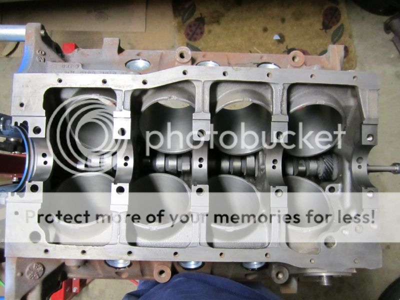
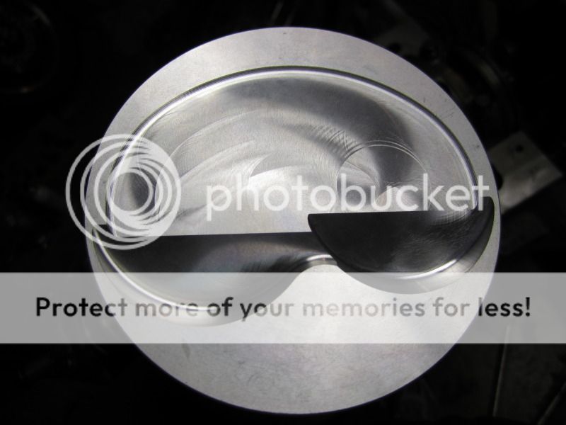
Keith Black Hyperuetectic pistons with a lower 8.5 to 1 compression for future blower installation. Not building a race motor, so I think I can squeak by with less of a squeeze for now. Matching Keith Black Moly rings.
Scat 3.25" stroker crank puts the cubes at 331 inches. No machining required on the block. Drop-in horsepower, LOL. Comp double roller, Scat matched set 5.4" I-beam rods w/ARP bolts everywhere. Everything balanced as an assembly from the balancer to the flywheel, like it should be.
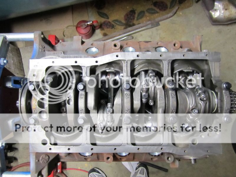
Big holes in that crank, but sometimes the lower end stuff needs a little extra time. Won't know til the key is turned of course, but I have warm fuzzies instead of butterflies most of the time when I look at the pictures.
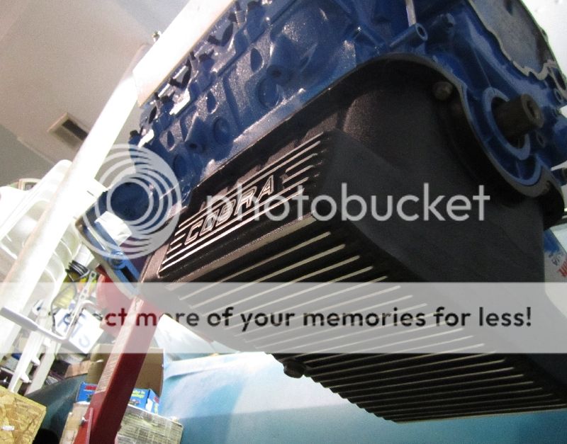
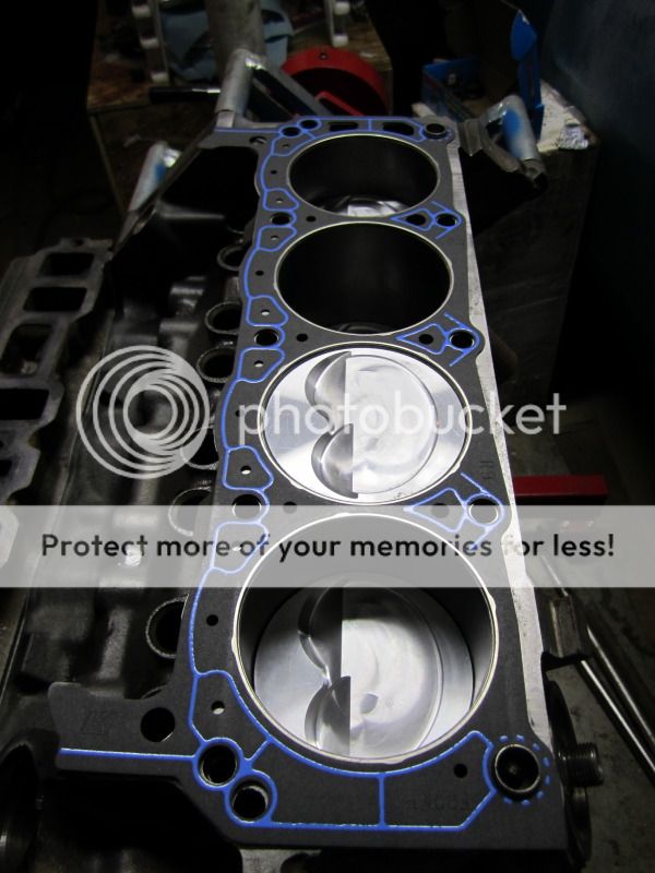
Fel-pro gaskets....
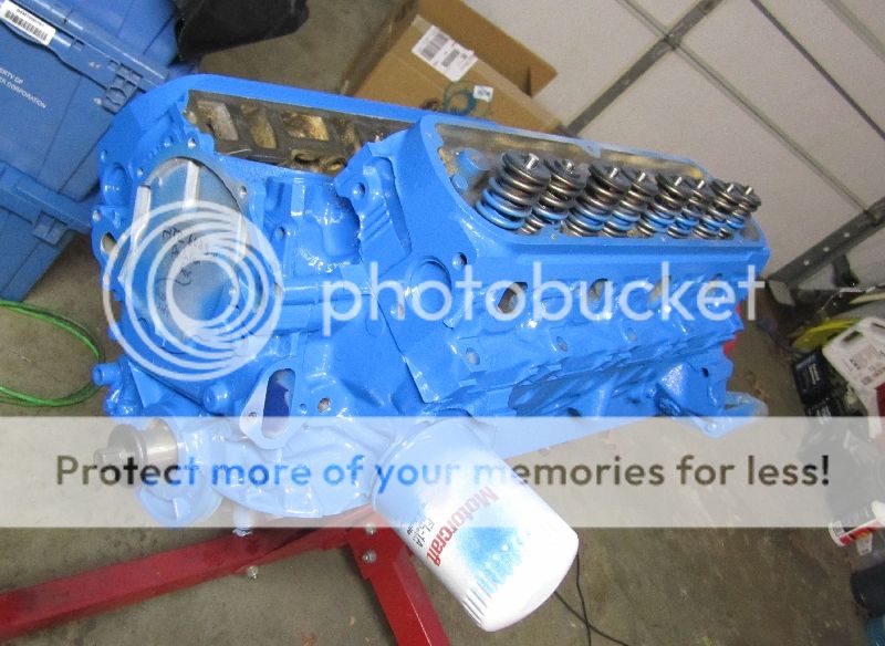
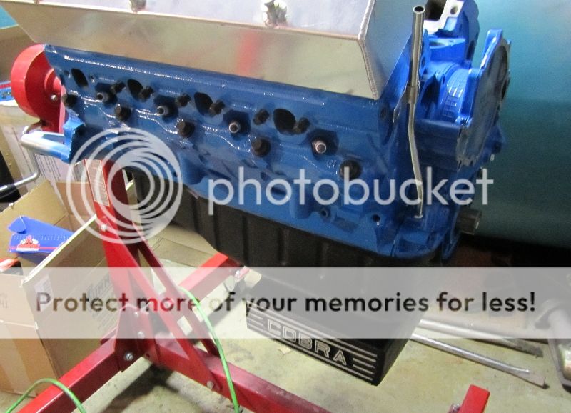
A set of GT40 heads from an F150 Lightning top off the long block. Primer coat done. Waiting for paint....
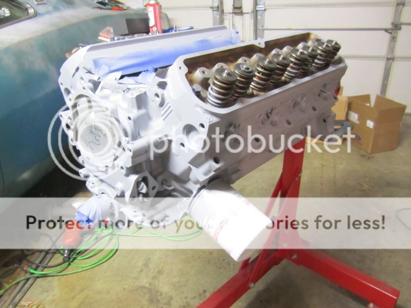
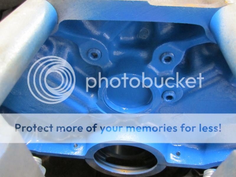
I had thought about the engine color for a looong time. Had wanted a light blue or sky blue. Turns out one of the Ford blues is just ticket. It's a little darker in person, but it works in keeping with trying to keep the all-Ford theme.
I had some issues with the Comp cam and timing set. Having worked in the parts department at a Ford dealer for 14+ years now, I'm hip to some of the funny business that the Blue Oval folks thought were good ideas. I thought a 302 would be a simple build. Maybe not quite as simple as a 350, but close. It wasn't. One piece fuel pump eccentrics, 2 piece fuel pump eccentrics, 3 or 4 different timing pointers, water pump inlet on the left, water pump inlet on the right......ungh. After I put the cam, crank, rods and pistons in, the timing set was next. Problem was that the cam timing gear pin wouldn't engage the gear far enough. Barely a sliver. Found there are 2 different length cam pins from Comp. Problem was, I was already using the longer pin. Spent a week researching everything I could, talked to the guys at Comp and everyone was at a loss as to what my problem was. One night it hit me. Check the old cam. Since this engine was complete, and it all came apart without problems, then I should be able to use the old parts as a baseline. Luckily, I hadn't thrown anything out. Turns out the new Comp cam had its hole machined a bit deeper than stock. Crap. Rather than deal with taking it out and dealing with Comp, I simply welded onto the end of the pin to increase its length about an 1/8th of an inch. Machined the end so it fit the deep end of the hole and I now had the pin fully engaging the timing gear. Crazy.
September 2011
After what seemed like an eternity in finding a suitable block to build, the next question was where to have it machined. Maybe I was just out of the loop, but it felt like the number of quality machine shops had dwindled a bit. Not needing anything bored or decked for a loooong time though, there really hadn't been much need to know. I started asking around, calling a few of the performance shops. Well, ok. The one performance shop. In addition, I posed the question to some of my gearhead friends and one name kept coming up more than others, and one that I had heard about many moons ago. Turns out, the air-cooled VW shop in KC has a machine shop with a dude that knows a thing or two about American V8s. Went in to talk to him and there were some nice projects going on. Big block chevy for a '70 Chevelle, Flathead....lots of goodies. Dropped all my parts off and waited for the phone call. Couple weeks later it was ready.
.030" over and clean enough to eat off of. Cam is a Comp X-treme Energy hydraulic flat tappet (old school-like). 1300-5600 rpm range with a .493/.500 lift, 262/270 duration. It's very similar in spec to the Motorsport E303 cam that most of the 5.0 Mustang guys run. I think it'll have enough of a lope to let you know it's alive.
Keith Black Hyperuetectic pistons with a lower 8.5 to 1 compression for future blower installation. Not building a race motor, so I think I can squeak by with less of a squeeze for now. Matching Keith Black Moly rings.
Scat 3.25" stroker crank puts the cubes at 331 inches. No machining required on the block. Drop-in horsepower, LOL. Comp double roller, Scat matched set 5.4" I-beam rods w/ARP bolts everywhere. Everything balanced as an assembly from the balancer to the flywheel, like it should be.
Big holes in that crank, but sometimes the lower end stuff needs a little extra time. Won't know til the key is turned of course, but I have warm fuzzies instead of butterflies most of the time when I look at the pictures.
Fel-pro gaskets....
A set of GT40 heads from an F150 Lightning top off the long block. Primer coat done. Waiting for paint....
I had thought about the engine color for a looong time. Had wanted a light blue or sky blue. Turns out one of the Ford blues is just ticket. It's a little darker in person, but it works in keeping with trying to keep the all-Ford theme.
I had some issues with the Comp cam and timing set. Having worked in the parts department at a Ford dealer for 14+ years now, I'm hip to some of the funny business that the Blue Oval folks thought were good ideas. I thought a 302 would be a simple build. Maybe not quite as simple as a 350, but close. It wasn't. One piece fuel pump eccentrics, 2 piece fuel pump eccentrics, 3 or 4 different timing pointers, water pump inlet on the left, water pump inlet on the right......ungh. After I put the cam, crank, rods and pistons in, the timing set was next. Problem was that the cam timing gear pin wouldn't engage the gear far enough. Barely a sliver. Found there are 2 different length cam pins from Comp. Problem was, I was already using the longer pin. Spent a week researching everything I could, talked to the guys at Comp and everyone was at a loss as to what my problem was. One night it hit me. Check the old cam. Since this engine was complete, and it all came apart without problems, then I should be able to use the old parts as a baseline. Luckily, I hadn't thrown anything out. Turns out the new Comp cam had its hole machined a bit deeper than stock. Crap. Rather than deal with taking it out and dealing with Comp, I simply welded onto the end of the pin to increase its length about an 1/8th of an inch. Machined the end so it fit the deep end of the hole and I now had the pin fully engaging the timing gear. Crazy.