Ron Pope Motorsports                California Custom Roadsters               

Jag rear

Well, I don't have the CAD file on my home computer either, or I have totally spaced the file name. Anyway Ron, you just need to keep the axis of your pinion shaft fairly close to parallel to the axis of the tailshaft of your tranny. One or two degrees is close enough. The offset of the pinion to the passenger side will give you the necessary differential to spin the bearings in the U-joints, and you shouldn't get any weird vibrations. George, wouldn't you agree?
 
That's pretty much what I found out from the sites I looked at yesterday. I think I've got a good understanding of how to set this beast up now. tomorrow is my last day of work so I can start pushing on this and my retirement at the same time. I'm looking forward to both of them.

Ron
 
After looking at George's cad drawings I decided to make up some brackets and build a mock rear frame. Here are my brackets;

JagT001.jpg


I had to change my bracket design a little in order to be able to mount the pinion struts. At first the center section was in front of the cross member. Now it's under it. When I cut down the pinion mount I left a tab to mount the brake 'T' to. This also gave me a better location for the shock mounts.

The surface for the center section was at 95 degrees from the u-joint flange and the lower arms were 90 degrees from the u-joint flange, so I mounted the plate for it flat on the crossmember. I figure the frame will have a 5 degree rake to it so the lower arms will be parallel to the ground at the trunions.

JagT002.jpg

Center section mount and pinion bar and strut

JagT003.jpg

Shock mount

I haven't done any thing with the lower struts yet. I'm thinking I'll be able to run them up to the center crossmember with the trans mount there also. Those are the Jag coil overs on there for now. They will be replaced with Qa-1 adjustables.

I'm glad I decided to do this. Now when I build the frame, all the guess work for the Jag is done.

Ron
 
Beautiful work!! You could package that as a kit for guys that want to install a Jag rear end in their cars..
Chuck T
 
George's drawing doesn't show a piece that he decided to add to mine. I think it's probably pretty important for the structural integrity of the suspension. It is a plate that ties the two lower control arm trunnions together, similar to the original cage.
 
I noticed that in one of the pictures. I'll be doing some thing simular but not a full plate. More of a skelitontype of thing. The plate that was on the cage was made of 16g. I'm thinking a piece of 10g. Sorta like a rectangle with a hole in it and 4 arms going out to pick up the trunions. I realize I have some more engineering to do but I'm thinking the frame should come next.

What do you think of using some cone shaped washers on both sides of the heim joint at the front end of the control bars. That would let the body of the heim float completely round on the ball. If they are mounted in a sandwich bracket, it would also be a safety feature as it would capture the body if there is a failure.

Ron
 
Can't wait to see this up close. Great work.
 
CCR plans update. We had 3 xj6 rears in the shop and my son decided to put one under a 22 dodge bucket he is building. I had a set of the CCR plans so I made a copy then laminated them with clear shelf paper and cut them out. I hauled a chunk of 3/8 plate to the college shop. they have the plasma with the electric eye to copy the plans. I made 3 sets then junior cut up the stock jag cage to use as drill guides, use a transfer punch to get factory hole locations on the pieces. THE CCR Bottom links I had were not symetrical, I'll use the ccr info. the jag pieces and some cardstock paper and drafting tools to make my own pattern. the corvair patern wasn't close to my bolt holes. the hardest part was getting the top shock mounts in right. I might make a jig off the next stock cage for the next one ,,angle iron spreaders with tabs for the holes to hold everything square and be adjustable for spread.
 
GAB said:
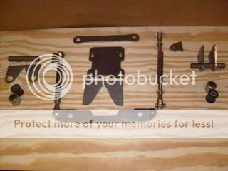
The tubing for the trailing arm is 7/8" x .156" D.O.M. so that it can be tapped 5/8-18 for the rod ends on the front. The drawing shows using a bushing sleeve for using the original Jag bushings or the delrin replacements that some vendors sell. The last one that I installed (Lee in K.C.'s) he used the Kugel adjustable rod ends on the back. If I remember right, I had to make up some spacers to make up for the difference in width between the end fitting of the lower control arm and the tab. The tube was left straight on that application. I assume that this is what you are referring to in asking about the insulator.


As to using just one coilover per side, yes you could probably get away with it with no problem, but be aware that Jag rears are rather weight sensitive. You will need to change springs to make up for the change to the design. I don't know that you would have to double the spring rate but a significant amount would probably be required.

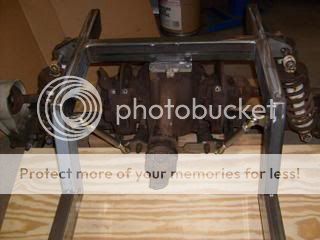
The amount of leverage exerted on the coilovers by the placement of the mounting point for the shocks in relation to the length of the lower control arm is quite a bit. The other thing that enters into it is the angle of the shock. The more angle in relation to the input of load results in the need for heavier springs to maintain ride height and ride stiffness.

A little bit of difference in the upper mounting width can mean more difference in ride than many people realize. That's probably why you see so many different opinions about which spring rates for Jag rears when that question is asked on one of these boards. It's kind of like the Harley coilover controversy. I measured one of the springs from a Harley and it was about 290# per inch. The generally accepted spring rate for coilovers with a straight axle rear on a bucket seems to be somewhere around 150#. I would think that there wouldn't be much "ride" when using the Harley units. But here again, there is leverage and angle in the mounting involved in the original application. Those definitely affect the choices to be made.

I've always been impressed with how English engineers do things very "properly". The Jag rear is a good example of that to me. All of the pivot points have needle bearings and seals. The use of the two shocks to balance the forces on the lower control arm. The entire assembly being isolated from the body structure and free to move but controlled with the paddle arms. But then too, they weren't designing an economy car.

Hope this helps...or at least doesn't confuse the issues too much more. :lol:

The Jag was not built for a Jag, but for a FORD cobra, the whole thing is american, gears and all.. then when cobra came out with horsepower, the IRS/jag rear was not soooo good any more... it is for cornering and comfort, why do all that expensive stuff to that rear end, when all you have to do is mount it all i nrubber, like it was designed to be, and go on and ride in comfort..??
 
i can't help but to wonder about all the jag rears out there that used the ccr plans to mount the irs.

ted...do you think if a urethane pad where placed between the center section and the mount it would make a difference??

you also where talking about the control arm running forward from the strut arms in another post. question: would bringing the arms in so they are 9 1/8 apart at the xmember help ? i'm thinking the control arm / strut would act like an "A" arm, eliminating the arc from a hair pin to the frame rail. your thoughts please.

gab...did you use the set up you showed in your sketch? if so, what kind of results did you get.

Ron
 
Jaguar had the independent rear suspension in production a full year on the 1961 XKE before Caroll Shelby received the first prototype body from AC Cars that became the Cobra.
 
Ron, GAB's drawing was for the set-up he did for my T. Been driving it for two seasons now and I have not had any issues. I have not experienced the noise issue Ted has mentioned, and my pumpkin is solid mounted to the plate on the crossmember. Re the forward mounting points for the radius arms... yes, they need to match the swing axis of the lower control arm trunnions for the reason you stated.
 
thanks lee.................................

Ron
 
In my opinion, and that is all that it is, I don't think that many people can hear or feel any noise or vibration transmitted by a solid mounted independent rear in a BUCKET.

A closed car is another matter though. All of the units that I made were used in later street rods('32's to fat fender stuff). Trying to mount one in rubber in a bucket is not very practical as far as I'm concerned. You cannot depend on a rubber mounted crossmember to maintain the necessary frame integrity and there just isn't enough room to get another substantial crossmember along with the bushings and upper shock mounts in the limited rear kickup space in most buckets.

The Snow White type of mount with the rubber insulators right next to the third member can allow some side to side movement of the whole rear end when side loading is applied.

Ron, yes I used the radius rods that ran forward to the frame rails on the units in the drawing. Remember that the crossmember and the rear end unit are free to move on the rubber bushings to a limited degree. The radius rods control that movement and limit it to the small fore and aft amount that is described by the radius length of the rods. Loading on the rod is primarily tension and compression, no bending load to speak of.

Wonder how come everyone refers to them as Jag rear ends rather than Shelby Cobra rear ends? :)
 
Check it out.. They are all American and have Ford gears and some even had Ford posa-locks in them also... what they were designed for and what they end up in, are many times different... just like now, they have the turbo 400... If you just use the CCR plans as they are, Some of those Roadsters are still running today, (14 plus years) WITHOUT radius rods, that work, only hanging on a slotted bracket,, just there for looks ONLY... and remember this, these rear ends are not made for drag racing... or supercharged engines, and the reason they wear the tires on the inside is because the cars are too low to get even tire wear, raise them up and tire wear goes away... follow one down the road and watch the wheels move towards the body when ever they go over a dip in the road or stand on the gas.... trying to keep the axles level is what kills tires...
 
Forgot to answer a question about putting something soft between the frame and the third member mount, not good... the third member needs to be tight and the bolts need to be wire tied so they do not get lose... as far as vibration goes, let a gear wear out and you will feel it for sure, other wise, the vibs cause small nuts to lossen up, like on the backs of gages , etc. and vibes causes Brass rads to seperate at the seams... Just too many opinions here to argue about this, so do your own thing, I will...or e-mail me for a 1 on 1... tedabrown@juno.com
 
I took some pictures at the Goodguys show in Kansas City of a very nice bucket with a Jag rear. It used a Snow White type of mount and a bolt on shock mount that sounds like it may be similar to GAB was talking about in the other post.
IMGP5381.jpg


IMGP5390.jpg


IMGP5733.jpg


IMGP5727.jpg
 

     Ron Pope Motorsports                Advertise with Us!     
Back
Top