Ron Pope Motorsports                California Custom Roadsters               

Jag rear

Joe... I've studied the pics of your car as well, and yes, it did answer some questions. I like the look of the newer Micky Thomson tires, but I haven't yet decided a theme for the car. If I go with a '70's look, then something of a more traditional tread would be used. If I go with a more state of the art look, then the Micky's would be my choice. Why do you ask?

Ron
 
Here are some pix. Please ignore the oil puddle under the rearend :eek:. I inadvertantly bought a rearend cover that doesn't have a vent, so my pumpkin is pressurizing and forcing oil out.
 
Mine is stock width. It came out of a '77 XJ6 and is 61.5" hub to hub. I have thought about narrowing it, as I would like my tires closer to the body.
 
Great pics Lee. Just a couple of questions if you don't mind. How much kick is in your frame? When I took a rough measurment of the distance between the upper shock mounts , I got something like 28". The questions are 1) how wide is your rear crossmember? 2) how far apart are these mounts on your car?

Ron
 
OK...Thanks again Lee! Let's see what I can do with all this great input.

Ron
 
Here are some more photos of Lee's installation.

irsmount003.jpg


irsmount005.jpg


irsmount007.jpg
 
Wow ...You guys are making this really easy! Even so, I've got a couple more questions.

1.) Is the kick 60 degrees?
2.) How much drop in the center cross member?
3.) Is Lee's body a standard or streched one?
4.) How long are the trailing arms?

How can I ever thank you for this info?

Ron
 
I am assuming the pinion is 3 degrees up. Does that sound right?

Ron
 
The problem that I see and I beleive that I have is that there is a lot of out side leverage on the bearings with the wider tires the load is in such a small area that it couses premature bearing wear and u joint wear. I had no problems with the smaller tires but when you 10 inchs to the outside I beleave we creat a problem. the bearing hub does not spread the load as a streaght axel rear. But it looks cooool functional YES reliable NO. If you go with the smaller wheels and offset you should not have any problems. Just my thought Joe
 
Joe, a couple of thoughts about your excellent points. First, if you study the Jag geometry, you'll see that it is designed with slight negative camber. This puts virtually all of the weight on the inside of the tire. Almost every Jag-reared hotrod I've ever seen that had wide tires and some mileage on it has more wear on the inside of the tire, so this would seem to bear out the idea that the negative camber loads the inside of the tire. Depending on the backset of the wheel, I would guess that the contact patch of the wide tire is very nearly the same as the narrower tires. Secondly, when you consider our Ts weigh less than half of the original car the rearend was in, I wonder whether we really need to be concerned about accelerated wear on the bearings and u-joints.

A buddy of mine has had a Jag in his T for over 13 years and has always run the widest tires available (Mickeys, Pro-Tracs and now Hoosiers), and he has had no problems with bearings or u-joints. He does, however, have accelerated wear on the inside of his tires. :D
 
I'm about to set up the rear cross member. Can anyone tell me if the center section is set at 3 degrees up at the U-joint yoke? I'm figuring the frame at a 5 degree rake and the mount set at an 8 degree total aditude. I have some adjustment features in the mount, but the closer I can get, the better.

Ron
 
Ron,

Not sure if I've understood the question correct but here's my view on it.

I got a feeling the yoke should be vertical and the diff mounting is set at an angle (can't remember what now!), I guess you know the mounting and yoke are not at 90 deg. I know there was a lot of discussion of one of the UK sites but I can't find it now. I think I measured my angle from the cage that the axle came in. If you get the mounting angle wrong then the springs bind unless you put the top shock mountings at the same angle. Does that make sense?

I'm no expert but it all made sense when i did mine.

Pete
 
Thanks everyone. I found the info on a Brit site along with an explaination why. Just what the doctor ordered.

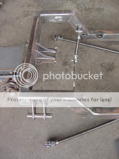
Got pieces made but afew more to go. I'll post pics soon. Keep watchin' George, I'd like to know what you think.

Ron
 
On Lee's car, he had some very specific locations that he wanted to place the rear end in location to the frame. That is the reason that the center section was cantilevered forward of the rear crossmember. Most installations in Buckets have the rear end unit pretty much centered on the rectangular tube. I milled a flat on the mounting plate that was at a 5 angle to make up for the fit up to the crossmember. That is what the drawing shows but I don't remember if that was only to take into account the mounting surface on the center section or if it also included a bit of angle for the pinion. The pivot shafts for the lower control arms (inner & outer both), the upper and lower shock mounts and the pinion are all parallel. The only angularity is in the top mounting surface and that is not in all of them. Some had a mounting that was parallel with the rest of the unit...XKE's if I remember correctly.

CenterSectionMountingPlate.jpg


I have to admit to not being concerned about pinion angle as much as most street rodders are. Race cars are a different deal. Why? How many cars (rods & stockers) have had parallel rear leaf springs on them. What happens when you accelerate with that type of unit? The pinion tries to climb the ring gear and the springs "wind up" to some degree resulting in a change to the pinion angle. Braking produces the opposite reaction. How many times would this occur in a trip across town? I don't recall u-joint failure as being considerable with that type of spring configuration.

I once saw some info on agricultural driveshafts for running grain augers and other PTO driven equipment. They don't even make much difference in the amount of H.P. that they they eat up until you got up to angles like 15. Just back the tractor up until you're close and hook up the drive shaft. :D
 
George, I'm thinking I did a CAD drawing to figure out the mounting angle of the plate. It's not here on my office computer, so maybe it's at home. Since I had already built the car with a straight axle rear-end and had exactly the stance and wheelbase I wanted, I located the mounting plate to replicate the wheelbase and took the rake of the frame into account. I was more concerned about keeping the swing axis of the lower control arms close to parallel with the ground than with pinion angle. Since the pinion on the Jag is offset to the passenger side, I wasn't worried about including pinion angle to get the bearing movement in the U-joints.
 
Ok...What I've found out so far is that the u-joint flange is at a right angle to the plain the lower swing arms are on. Because of this the flange needs to be at 0 degrees. When the engine is being mounted, the output shaft on the trans also needs to be at 0 degrees. With the engine centered in the chassis and the offset on the center section, plus the fact that the engine is at a different heigth than the rearend, The U-joint work in phase. The only other thing to concider is that the trailing arms are as close to level as possible or at least where they mount to the frame. This point should also be in line with the inboard pivots of the lower swing arms. It's not much different than setting up an IFS. At least that's what I've learned or read today.

Ron
 

     Ron Pope Motorsports                Advertise with Us!     
Back
Top