Ron Pope Motorsports                California Custom Roadsters               

My jag rear radius rods

Al,

You are totally loosing me when you talk about the lower locating arm being "variable length". It's a solid hunk of steel, the inner end has two pivots off the diff, the outer end has two pivots at the stub axle carrier. It travels in an arc as the wheel moves up and down, and the axle shafts travel in a parallel arc maintaining a verticle wheel. I just don't see any "variable length" parts here at all. If the lower locating arm and radious rod form an 'A' member, then yes, the front pivot on the radious rod must be in alignment with the two inner pivot points of the lower arm (blue line on drawing). Now if the radious rod is connected to something other than the outer end of the lower control arm, like for example the sub axle carrier, all bets are off. But I think in keeper's case the radious rod is connected to the lower control arms outer end, so it's a big 'A' and he should be good to go.

Youngster,

The weight of an XJ6 sedan is "heavy". Around 4250 lbs if I recall. About a 60 40 distribution, so the rear is looking at carrying about 1700-1800 lbs, empty. I don't think that is really relevant to this issue though.

Ted,

As mentioned before, Jag used a radious rod that was basically out of alignment, being that it went straight forward, but is was mounted in some really gooshy rubber mounts, it did little to carry the acceleration and braking forces until they were in the extreme. Many cars use a rubber mounting of all suspension parts to reduce road noise isolation more than anything else. Some even use double rubber isolation, but you and I can't afford many of those cars. HA! While you are correct about rubber making things harder to break, it's really not that simple. The sudden impact forces will be lessened, but the major ultimate force still gets through, so things like mounts, welds, etc., still get the ultimate force applied to them. They just don't get the hammer like pounding of smaller forces with rubber mounts. So, while I agree with you, I also must disagree with you. Fun, ain't it! I'm not knocking rubber at all, in fact I used to carry one in my wall... BIG Whoops... Sorry...

CB
 
Al,

If the radius arm's forward end is mounted in line with the pivot points of the lower control arms on the center housing,the rear atachment points for the radius arms will swing in an arc inside of the arc the lower control arm makes. This same principal was employed on the early Mustangs front suspension where Ford used a strut from the lower swing arm to the frame. The failures that occured with after market kits there where because the strut mount on the chassis was not in line with the pivot point on the swing arm.

Ron
 
Al, Sorry but if it is mounted like a factory setup, the radius rods (which I call flapper arms or control arms) mount straight forward of the hub, just clearing the rear tire... No kind of radius rod helps in the least with traction on this Jag type rear suspension... This is a ride setup, not traction, built for COMFORT!!! :)

Ted, I agree with you that the best solution is a radius rod mounted parallel to the direction of travel at the center of the hub is the best solution, but I must respectfully disagree about providing no aid to traction. The lower control arm mounting has some flex as it is a rubber bushing mount with a lot of leverage. Add wide tires and lots of torque and some fore and aft movement will occur resulting loss of traction and wheel hop. The latest Jags have redesigned the mounting system (I think they refer to it as the third generation design) to address this situation.

My thoughts are confined to Keeper's original post which I interpreted from his last post that he intends to run as is at this time. I hope he checks the setup and lets us know the results. I for one would be very interested to know the results.

Al
 
Al,

If the radius arm's forward end is mounted in line with the pivot points of the lower control arms on the center housing,the rear attachment points for the radius arms will swing in an arc inside of the arc the lower control arm makes. This same principal was employed on the early Mustangs front suspension where Ford used a strut from the lower swing arm to the frame. The failures that occurred with after market kits there where because the strut mount on the chassis was not in line with the pivot point on the swing arm.

Ron

Agreed, this is why there is bind in the setup as shown. A possible solution to solve the bind problem is to allow the locating arm to slide in and out of the rear mount as it lengthens and shortens with suspension movement. There is also a small amount of rotation that must be accounted for in making the mount on the lower swing arm. The arc is really three dimensional, but I chose not to address the second plane of the arc because the arm involved is quite long so the arc 's affect on the wheel base is quite small and the bushings should compensate for it. Ideally if the inner mounting were parallel to the ground and the lower control arm were also parallel to the ground the arc involved would keep the wheel base the same throughout suspension movement.. In Keeper's setup this is not the case so in a turn the outside wheel base would lengthen and the inside wheelbase would shorten which is actually beneficial, although the movement is so small it's doubtful it would be noticed.

I am still thinking about the angle and type of mount that would be the best for Keeper's current setup. Most likely his current setup should use a Heim (the actual type of bearing is a spherical plain rod end bearing, Heim is not the only manufacture of this type of bearing) end. I still lean toward a mount that the pivot is parallel to the blue line, but this creates another bend in the radius rod that affects its arc in a negative way if I am visualizing it correctly.

In reality Keeper should move on to a radius rod that is mounted to the hub at axle height and extends as far forward as possible and mounts to the frame at the same height as the axle. Not an easy fix on a bucket.

Al
 
As far as the so called "radius" rods aiding in traction, well I'm with Ted on this one. They are in fact control arms and their purpose is to keep the wheel and hub assembly located in the correct wheelbase location. They are attached to the hub and as such they see no torque forces from axle rotation/axle torque. Therefore they can't help in planting the tires for increased traction. All axle torque is delivered through the ring gear and center differential case. That case is bolted to the chassis either throught rubber mounts or solid steel bolts. These in effect cause the entire frame to be become one long single ladder bar or more correctly a torque arm. The only real loading forces seen on the control arms are straight line thrust loads from acceleration or g forces. For this reason these control arms do need to be large enough in diameter or design to prevent column buckling although I don't think a "T" would be a problem.

All IRS Corvettes up till the C-5 series used a single syle or a 4 link system that ran straight forward and was pretty much parallel with the frame centerline. I was thinking the Jags triangled inwards like the above drawing but I could be wrong on that. So until I have further information I will hold off on any opinions on that subject.

One other thing on the subject of braking forces. Corvettes had their brakes mounted out board at the wheels so that when the brakes were applied the control arm did absorb that torque reaction. The Jag on the other hand had their brakes mounted in board so their brake reaction was absorbed through the differention and that long torque arm, the frame.

Hope this gives everyone something to think about. I am open to comment and other opinions on this subject but I might be slow in responding in the coming week. Now get to thinking.

George
 
Al,

You are totally loosing me when you talk about the lower locating arm being "variable length". It's a solid hunk of steel, the inner end has two pivots off the diff, the outer end has two pivots at the stub axle carrier. It travels in an arc as the wheel moves up and down, and the axle shafts travel in a parallel arc maintaining a verticle wheel. I just don't see any "variable length" parts here at all. If the lower locating arm and radious rod form an 'A' member, then yes, the front pivot on the radious rod must be in alignment with the two inner pivot points of the lower arm (blue line on drawing). Now if the radious rod is connected to something other than the outer end of the lower control arm, like for example the sub axle carrier, all bets are off. But I think in keeper's case the radious rod is connected to the lower control arms outer end, so it's a big 'A' and he should be good to go.

Youngster,

The angle of the pivots changes the length of the lower control arm, which in turn changes the angle of the hub. This is necessary because the axle is a fixed length and if both had a fixed length the tire would not remain perpendicular to the ground. As the suspension is compressed the lower control arm lengthens and as it unloads the arm shortens. The measurement is taken from the bolt on the differential to the bolt on the hub. I would be interested to know the change in the length of the lower control arm over 4 inches of wheel travel when the suspension is compressed and unloaded. If it encourages someone to measure it just to prove me wrong I guess its 3/4" in each direction from the axle set parallel to the ground.

Ralph Nader's Unsafe At Any Speed killed the Corvair because the first gen had a setup that did not keep the tire perpendicular to the ground, commonly called a swing axle, which acted as a pole vaulter's pole causing the vehicle to roll over. Volkswagon had the same setup as the Corvair at the time and it had one mention in his book were he said anything I have said about the Corvair is ten times worse for the Volkswagon . But the media ignored this one sentence as it was much more popular to hit the giant GM.

Al
 
All that was needed to stop the roll over or tilted wheel problem was travel stops... With a VW all it took was a strap next the the torsion plate, to keep the movement in check... Just needed to stop that up or down movement before it got out of hand... There is a T Bucket with a Corvette IRS that sits with a ton of + camber,, the top of the tire almost touching the body, and gets even worse when two big guys get in the car, that is also very hard on bearings, and wheels...
 
Inboard calipers do transfer the forces to the chassis on this type of set up. Dont forget, however that its the trye contact that is doing the stopping. So there is a twisting action between the tyre and the caliper which will act on the bottom arm (dog bone) and the drive shaft.
On my set up there is an additional location. That is the bell cranks, which fits in to the back of the hub carriers, using engineering plastic as a 'bush'. These help stop the rotation of the hub carrier under acceleration and braking. Its like an additional radius rod. So in reality my back end (no not mine, the Ts) has 4 bolts on the diff pad. 2 ties straps to the diff nose and 2 locations on the center line of the hub carriers which act against the carrier rotating under acceleration and braking.

Gerry
 
Al, are you talking about the distance from hub to hub changing as the suspension cycles?

Ron
 
Al,

I think I see why we are at odds on this. If you will please go back and look at Keeper's pictures again, you will see that his radious rod is attached to the outboard end of the lower control arm, not the stub axle hub carrier. That makes all the difference. IF his radious rod were attached to the stub axle carrier, then of course there is NO arc that would match that of the axle and lower control arm except one that is parallel to those parts.

So YES, you are correct if Keeper had connected the back end of his radious rods where Jag connected them, but he didn't do it that way. Since that is not the case here, the lower control arm and the radious rod can be viewed as one piece, and further, togther, they become an 'A' arm (in fact they could even be welded solid there if he so desired).

Go back to the pictures please, and confirm for yourself the location of the back end of Keepers radious rod.... Stock Jags did NOT connect this way, their trailing radious rod connects to the stub axle carrier, so their "radious rod" (which points forward) doesn't swing in an arc that matches anything, but their big gooey rubber bushes and limited action allow this. Gerry's total removal of those means that there are acceleration and braking forces (fore and aft) plus twisting forces applied to the lower control arm, and he has rightly beefed it up a bit. Wheather it will cause hop or not when extreme forces are applied is yet to be seen, but "normal" driving should be just fine.

If I am wrong on where Keeper has connected the radious rod at the rear, I appologize, but the pictures would indicate otherwise.

Corley

PS Ralph Nader was an idiot, BUT, in the case of the VW, it had a downward hard stop for suspension travel. As the torsion arm when down, it hit against this absolute stop, limiting the travel. Corvair only had the shock to limit it. When the shock broke, the wheel could totally fold under the car. I've used both in various dune buggies, and am very familure with them. Corvette rear suspension is a different animal all together, and shouldn't be compared to either of those nor the Jag. It's just very different from any of those and has it's own foybles. I own two 'Vettes right now and am very familure with those as well. Really, they are not much like the Jag. They do rely on a trailing arm, and mis-alignment is accounted for in a different way. None of that really has much of any bearing upon the Jag radious rod issue, nor does discussion of the rubber bushes. Those would seem to be different topics to me...
 
Corley
Well said my friend. I can only say that if you look carefully at my set up the bell cranks move in the same plane as the hub carriers, so your observation about the connection to the hub carrier is completely correct. This is not about dimensions changing its about conflicting arcs.

I will let you know if I suffer from axle hop. Be assured i will tell everyone if I got it wrong. Just so they dont do the same thing and make the same mistakes.

Either way I am happy with my set up and no amount of unsubstantiated criticism from others who dont bother to post any details of their set up, or mistakes will make me (or I suspect you) go a different way.

I looked at the original title for this post and I am not sure there will ever be an end to it.
Gerry
PS I think you may be right about your suspicions regarding an ego thats bigger than the internet.
 
Gerry,

How come you are not at the wedding? Loose your invite? HA! Thinking about that other 'T', if it's for sale for $28k, then probably $20k would buy it. A lot of people put more than that into a build and don't come out with something that nice. Maybe you should buy it after all (for the little woman). Here in the USA we are on hard times, but from the look of the wedding you guys seem to have tons of cash! HA!!!

Corley

While I wish the 2 over privileged young uns all the best in their life together I am PROUD to say i have not watched one second of their over indulgence, at our cost. Finishing of my tank perch gives me more enjoyment than they ever can.
If they are lucky enough for the media and public at large to give them some freedom and they dont keep taking our money to support their way of life then I for one wish them the best.
Dont mind the Queen but all the rest can work for a living like the rest of us.

Gerry

PS sold my invite to buy a new distributor cap
 
OK- here is the thing-- IF you want -A- corner and ride car, put an IRS, if you are drag racing, put in a live axle 4- link, An IRS adds extra weight. Also , the IRS unit is--complicated -more moving parts can fail.
 
keeper did use the stock location on the dogbones. There is a small tab there that accepts a shoulder bolt that threads into the outter end of the arm.

Ron
 
Also , the IRS unit is--complicated -more moving parts can fail.

Yep
I have the same set up as millions of modern cars on the road today. A couple of extra UJs and some pivots... Go Figure
Gerry
 
Don't ya just love a challenge!!!!

Ron
 
Also, the IRS unit is--complicated -more moving parts can fail.

Oh my goodness! :hyper: I guess I better take out my Jag and go back to the S-10! Hey T-odd, can I trade you back for that S-10 axle? I got a Jag I'll trade ya. But be forewarned... it is complicated and has more moving parts that can fail!!

:rolleyes:
 
Lee, I love it, you have a great sense of humor, and your rear end seems to be holding up pretty darn well, so, just keep an eye on all the mounting bolts... You already know for yourself, just how strong the stock control arms are... I am just saying IF I were to build myself a new car and wanted to use a Jag rear, I would change the way I used to mount them, and would now do it like the factory mount, but try and make it look trick like your's is now...
 
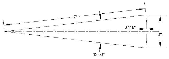
Here is what the movement is for the lower control arm at 4" of vertical travel which is a bunch. Less than 1/8" per side. The 17" is the center to center distance between the inner and outer pivot shafts on the lower arm ...if I remember right.

JagArc.jpg


The other thing to note is angle of the movement. 13.5 degrees is what would be required for the 4" or vertical wheel travel and a 5/8" Spherical Rod End Bearing allows 16 degrees of misalignment. No problem there.
 

     Ron Pope Motorsports                Advertise with Us!     
Back
Top