Ron Pope Motorsports                California Custom Roadsters               

English Wheel Build

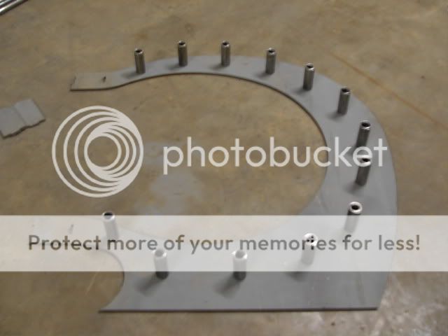
Ok for 8 years or so I have been DIEING for an English Wheel. I've draw up CAD files of them and changed it here and there etc. Well today I happened to be at Oneal Steel and they had a 4' x 47" drop of 5/16 plate. So I got it at scrap prices and only paid $80.00 for it, WOW!!

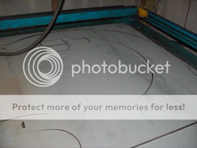
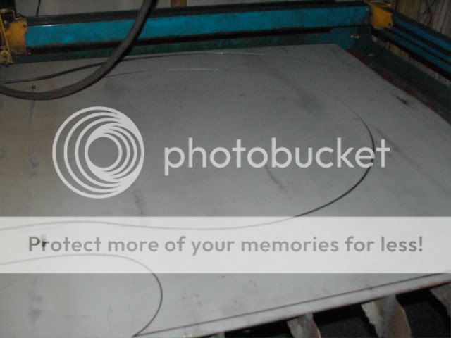
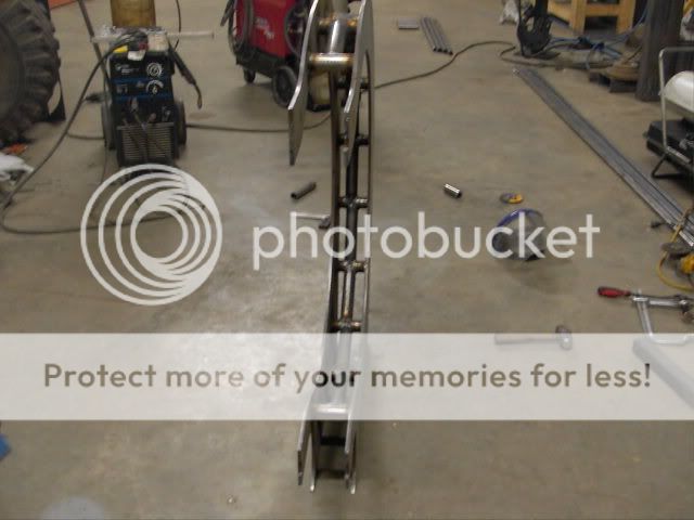
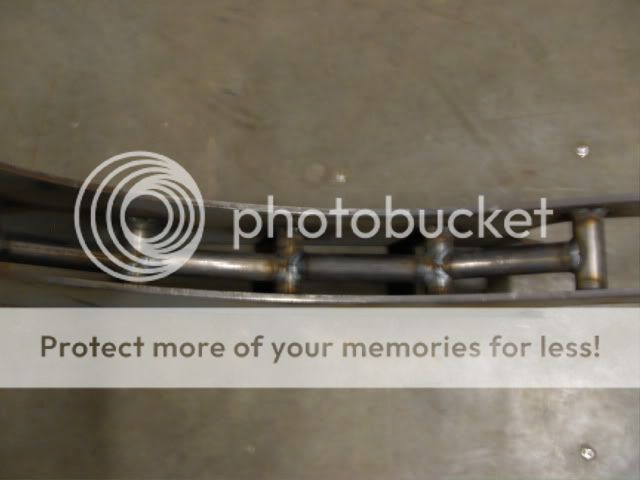
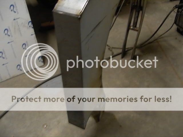
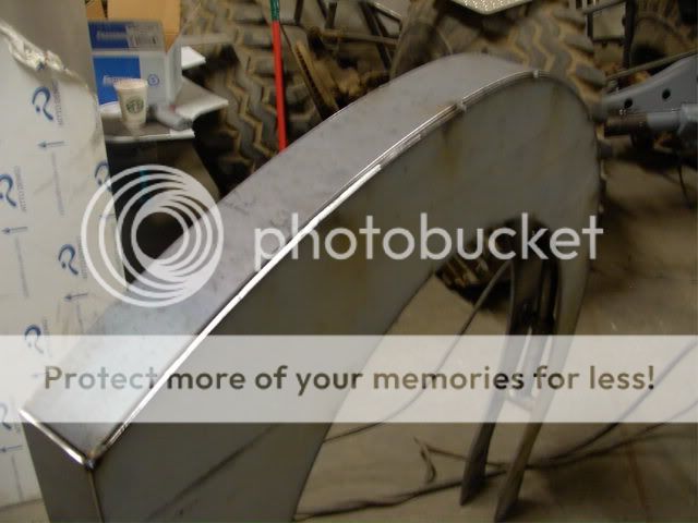
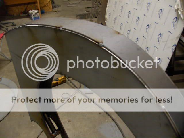
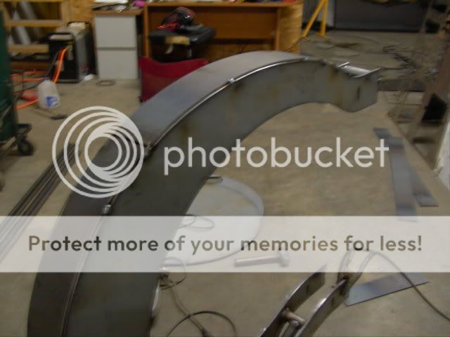
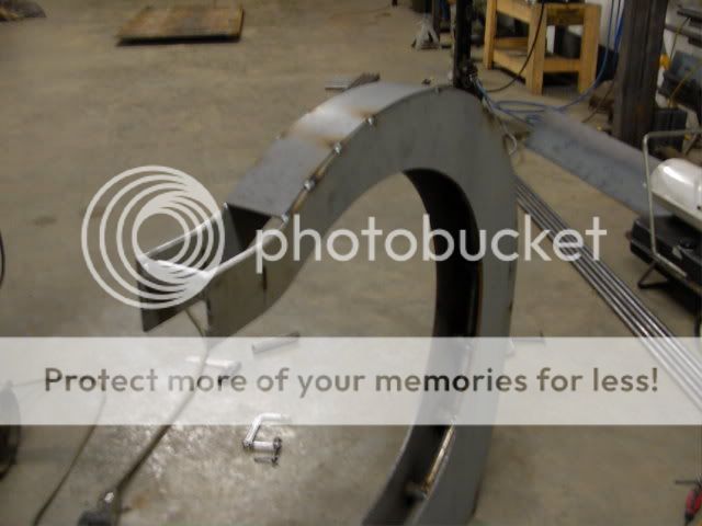
Anyway, so I start cutting the main part of teh E Wheel out.
PDR_0827.jpg

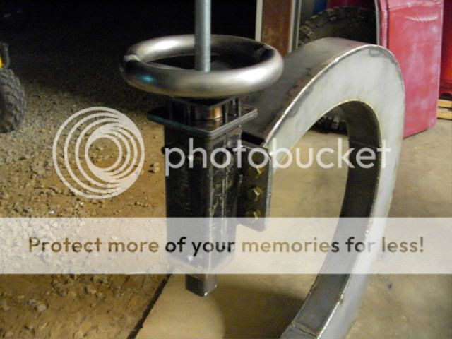
Here are a couple others when its done.
PDR_0828.jpg

PDR_0830.jpg


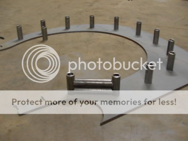
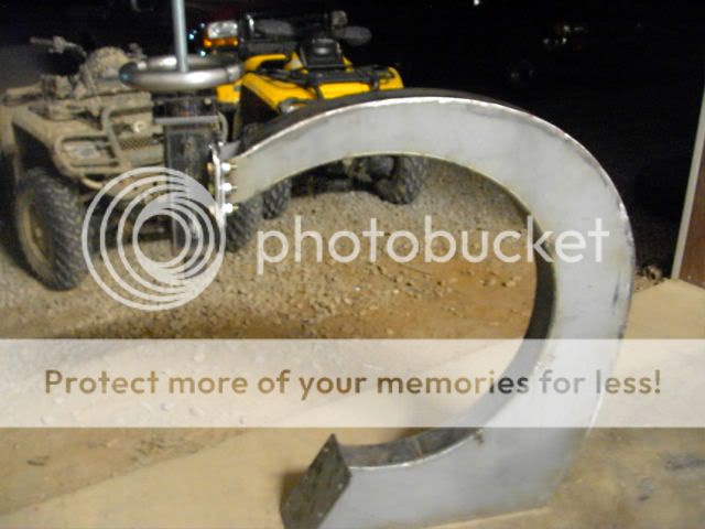
layed out on the floor.
PDR_0831.jpg


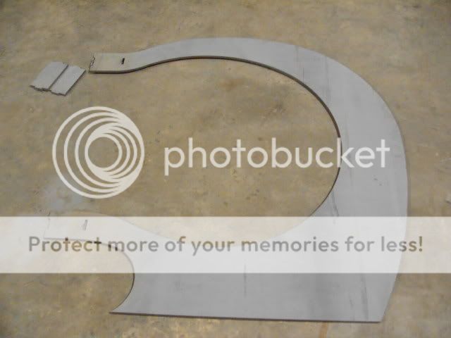
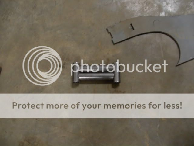
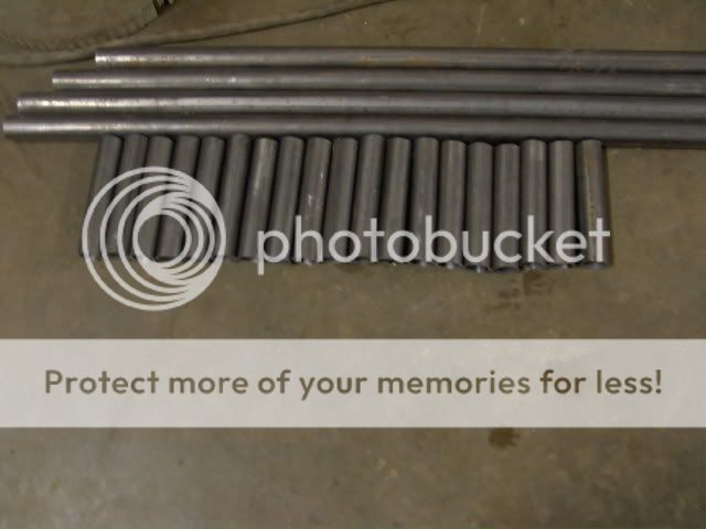
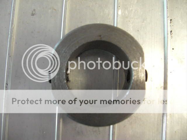
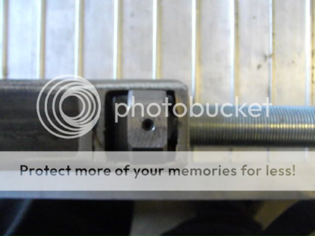
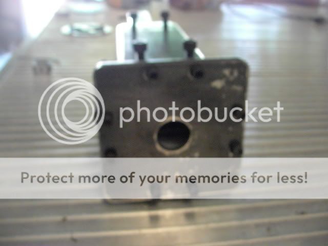
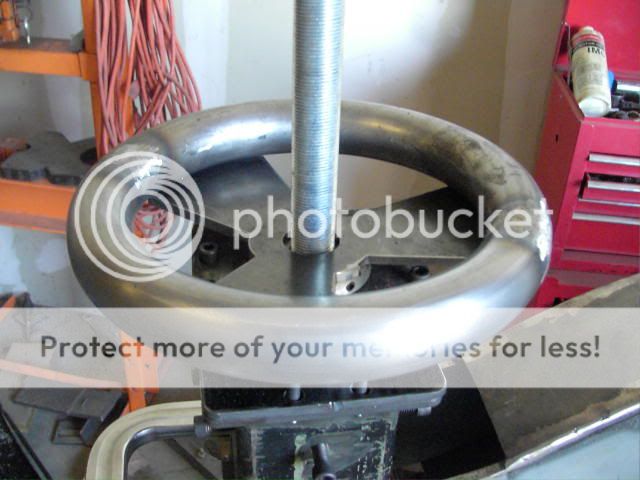
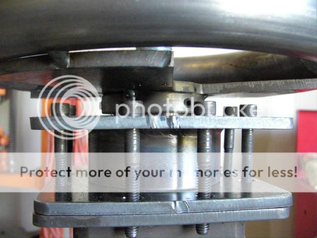
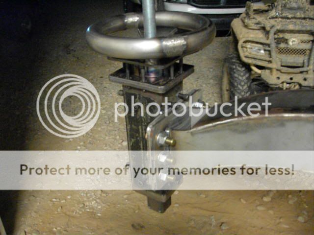
This is 4' x 4', ok ok more like 47" x 47". Now that I have that and the 1/4" x 2" x 2" Steel tube all I need to do is weld it up and order my dies.
I'll keep this updated.

I had a friend come help me load it on the table and while we were loading it there was a small booboo....

PDR_0825.jpg

Thats a 1.5" gash in my hand.
I had my friend handle the camer because I could pinch the skin and you can see everything in here. I thought it was kinda cool, Angela however does not.

PDR_0826.jpg
 
Yep I have the nuts AND the rod to do the job!

Ok so in between working on orders I got some more done on the English Wheel. I have to say though, this this is literally kicking my butt!!
PDR_0845.jpg

Late time I didn't yell scream or cuss, this time I did because it was a stupid mistake!
Anyway! Back to the project. My thought was instead of cutting holes and welding flat plate in I will machine down some tube then connect all the tube together like an inner skeleton system. So I machined down a bunch of tube to be exactly 4 inches. This will do two things, help me keep it evenly spaced and help it be rigid.
PDR_0836.jpg

Then I cut a bunch of tubes and will mill them down to be the exact same length as well so all the tubes are evenly spaced. Here is what it will look like.
PDR_0838.jpg

PDR_0840.jpg

Then I cut some 2" x 2" x .25" square long just to see where it will be going. I will pick the outer tube up tomorrow.
Also you can see my 6" x 1" ACME thread with 2 nuts. That was the shortest length I could buy at $70!!
PDR_0840.jpg

So tomorrow if I have time I will finish fish mouthing all these tubes.
PDR_0841.jpg

The long tubes in the picture go to something else hehe.
 
Well I got more done on the Wheel tonight. First I welded all the tubes together then I started plating the out side. I planned to plate it with 1/4" but I wussed out and had 3/16" and just used that. Enjoy

PDR_0852.jpg


PDR_0854.jpg


PDR_0855.jpg


PDR_0856.jpg


PDR_0858.jpg


PDR_0859.jpg


PDR_0860.jpg
 
Wow, I got a LOT done tonight. More than I thought I would get done. Can't find the camera but as soon as I do I'll post pictures.
Last night I cut all my UHMW and my upper tool assembly, drilled and tapped the holes.
Tonight I welded the bottom carrier of the upper tool assembly and sanded it down. Then I welded the upper part on that holds the 8 bolts and top. I also drilled holes and tapped the internal plates that hold the UHMW and bolted them together. I counter sunk the bolts in the UMHW so they do not hit the guild.
PDR_0900.jpg

Then I took my 1" fine thread and stuck it in the end mill and milled an eight inch flat spot on two sides. After I did that I took a piece of 2" cold rolled solid and machined it down. I put a 1 1/32 hole on the inside. Once down with that I put it in the mill and machined 2 more flat spots on the outside. I found teh center and drilled and tapped two 1/4" holes and put two set screws in it. Tomorrow I will cut my 2" tube to length and build the box to keep the bushing I just machined down and weld it to the 2 x 2 square. I have my upper wheel plates cut already and I will attach them to the tool post as well. Once that is down I will work on my lower arm.
PDR_0901.jpg

PDR_0902.jpg

PDR_0903.jpg
 
Ok as I was saying before.

This is the part that will house the part I machined down last night. I realized I need to machine another flat edge on it so it would fit hehe.
BEFORE
PDR_0908.jpg

AFTER
PDR_0909.jpg

PDR_0910.jpg

So it looks like this while inside the square tube.
PDR_0904.jpg

And this with the top on.
PDR_0905.jpg
 
My Next goal was to work on the Handle that actually moves the shaft. As you have most likely guessed, with the part inside of the 2x2" square it can't spin. Most English wheels I see as you turn the adjuster wheel it moves up and down. I wanted my wheel to stay in place and just wanted the threaded rod to move. Here is how I plan on fixing that.
First I took a piece of solid 4" cold rolled and machined down one side then bored a hole through the middle.
PDR_0911.jpg

Orginally as you can see the black sharpe marks I was going to machine down both ends. I changed my mind because I didn't really need to on the other end and I kinda changed plans through the 4 hours it took me to machine it done the way I wanted it.... Yes 4 hours total. I took one of the nuts I got for the threaded rod and machined it down until it was round. Then I machined down the fat part of the piece more then flippedit over and started boring it out with my boring bar. Once it was bored out enough for a very tight fit I pressed it in and welded it up.
PDR_0913.jpg

With a nut beside it.
PDR_0914.jpg

With a nut on top so you can see how it was going to be.
PDR_0915.jpg


I did go back and machine the tig weld down so it was smooth. Next I cut some square piece of UHMW traced a circle in it and started machining it down.
PDR_0916.jpg

I did two piece like this but one will have a MUCH larger hole. The bottom piece I did put a place for the machined down weld as it was raised a bit. Here is how the pieces go together.
PDR_0917.jpg

PDR_0918.jpg

PDR_0919.jpg
 
Ok I got more done today. First here is a better picture of the raised edge I was talking about last night. You should be able to see how I made a pocket in the UHMW for it.
PDR_0920.jpg


Now I took a piece of 3" x 1/4" tube and machined it down to be exactly 2 7/8".
PDR_0921.jpg

Then i welded it to the upper plate assembly. By the way this piece
PDR_0922.jpg


Goes over this piece.
PDR_0919.jpg


PDR_0923.jpg

Next I got another piece, yes I said ANOTHER piece of cold rolled solid and machined it down to fit over the smaller end of this part...
PDR_0911.jpg

Here is what it looks like.
PDR_0929.jpg

Then of course I drilled and tapped it in three places.
PDR_0930.jpg

Then I put two pices of tube and bend 180* in them then welded them together. I then went to the CNC machine and put out a piece that welds to the tube so it looks like a stearing wheel.
PDR_0932.jpg

Now you can see the complete assembly put on and working.
PDR_0931.jpg

Now I can turn the wheel and the threaded rod actually doesn't turn at all. It works even better than I thought it would.
 
Its getting CLOSER!!!! I so EXCITED!!!
PDR_0934.jpg

PDR_0936.jpg


As you can really see in this picture I cut off the front part and made some plates to bolt it up with. Yes I know I have to put a small fill plate on the top and bottom. I just wasn't sure how much I needed to plate in until tonight =)

PDR_0937.jpg
 
Looking good so far!....Its amazing how much time it takes to fabricate parts. Some people don't take this into account when they buy something. I know my customers don't...lol
 
Nice work, thanks for sharing. :)
 
So far i am impressed with your english fingernail remover sorry wheel.
 
this is a piece of 1" Acme thread. the threads are square cut and 5threads per inch. if that isn't Acme thread, you will be replacing it soon. it won't handle the load you will be putting on it. maybe it's just the picture (i really hope).


1inacmethrd.jpg


Sorry.

Ron
 
I actually have a full stick of ACME and intended on using it first. But I figured I would try the fine thread first. So far I don't like it at all. So I may be swapping the ACME in by the wend of the weekend.
 
go to the Acme now. i've tried the fine thread, just won't hold up.

Ron
 
Youngster said:
go to the Acme now. i've tried the fine thread, just won't hold up.

Ron


haha I actually am now. Playing with it last night I HATE the fine thread. HATE IT. so when I can work on it again I am going to replace it.
 
are you gonna build in some kind of quick release. comes in really handy when you are trying to fit a panel and need to check it often. don't have to reset the anvil everytime then.

Ron
 
with your adjustment on the top wheel you could use an eccentric disc on the bottom for your anvil wheel to sit on. in most cases you probably won'y have to drop any more than 1/2" or so. just guessing here.

Ron
 

     Ron Pope Motorsports                Advertise with Us!     
Back
Top