Cell phone stop watch?...and one of the odd ideas allows for aligning each side by itself, and requires only one tool you might have already. A hint: it's digital.
You are using an out of date browser. It may not display this or other websites correctly.
You should upgrade or use an alternative browser.
You should upgrade or use an alternative browser.
Lining up a new front end...how would you do it?
- Thread starter PotvinGuy
- Start date
roadmonster
Member
Of course. But that's easy. I did it about 6' from the wall, which equals a 6' straightedge. It agreed with my alignment jig down to the 1/4" toe-in.
fluidfloyd
Active Member
Of course. But that's easy. I did it about 6' from the wall, which equals a 6' straightedge. It agreed with my alignment jig down to the 1/4" toe-in.
Not questioning you by any means as I'm sure you knew what you were doing. More of making the point for those that have never used this method and are considering it. Thanks for posting this method!
George
One thing I failed to mention...This all works as long as the front axle is installed perpendicular to the frame center line. But having seen your car up close and personal I didn't feel it necessary. So you other eagle eyes remember to put your axle in square and centered. Just take your time and measure carefully then measure again. And before your buddy drinks that beer have him measure it. Hell have the dog measure it. One other pet peeve of mine. I have never seen a vertical mill or an engine lathe with fractional makings on the feed dials. Never saw fraction micrometers. So through those damn harbor freight tape measures away and get one that reads in tenths and thousands. So much easier when doing close and precision layouts like suspension work. I also don't weld metric but that's another battle. Now get to work.
George
But what if it is an old dragster and the front axle is 2" offset? With a 2" wheelbase difference from side to side?
fluidfloyd
Active Member
But what if it is an old dragster and the front axle is 2" offset? With a 2" wheelbase difference from side to side?[/QUOTE
George
Ron... You trying to bait me? Naw...you know the answer to this. A dragster is not dealing with cornering issues. Even though the spindles are offset, they are offset front to rear. Unless that chassis builder is blind or a poser then they should still be equally located from the chassis center line left to right. In a straight line they will still go straight. Back in the day a T/F rear engine car ran as much as 32-33 degrees of caster. As long as it left straight it would go straight. there have been several cases where steering wheels came off and the driver just coasted to a stop. F/C cars of the day ran from 32 to 15 degrees of castor depending on the driver. Large upper strength guys like Raymond Beadle etc ran them at 32 degrees. I only built a couple of the Fuel Coupes and both ran a lot of caster. I know some of the econo, bracket and comp dragsters run less castor but they don't have the top end speed of a fuel car. Biggest problem with the 32 degree front ends is slow speed turning in the pit area. Dragsters don't have much nose weight but make big radius turn. F/Cs tend to flop the wheels over and take some muscle to straighten back up. None that I'm aware of run any Ackerman. So how does this sound to you?
George
fletcherson
Well-Known Member
Sorry for the delay, just got in, looks like George covered it. I assume you are just trying to get them parallel to center them, the alignment shop will take it from there. If you try to get them centered to the frame, it could work against you if it isn't in alignment, the rest of it. You just neet to get them parallel to each other to set the steering arms from what I see.Trying to envision your idea. Clamp a straightedge to each rotor and then measure...from where to where?
fletcherson
Well-Known Member
I spent years in the building industry, and lasers are great for some things, but they are not exact. We once tried to use a laser to set up a x Ray room with disasterous results...String, levels, plumb bobs, analog transit, and water levels are my pick for accuracy as long as the wind isn't blowing, then there is no one to blame but the operator, lol. .25 inch is standard variation for every laser I have seen for building, etc, and that's fine for laying out a foundation or setting piers, not so good for a front end alignment. There are specific use lasers that are accurate, but they are not practical for most of us to afford.When I built dragsters (aka NHRA Jr. Dragsters) I used string, 12 pound fishing line. Then I got a laser. I soon came to find that the laser that I could afford had a +/- of about .250 inch out at 25 feet. We tried a 2 power rifle scope to align Bell Helicopters 206 and 212 main rotor heads, but we fell back to the string method. getting the precision out of the scope mount was difficult.
fluidfloyd
Active Member
roadmonster
Member
String is great if you're building a shed.
fluidfloyd
Active Member
String is great if you're building a shed.
I was thinking fishing but shed building will work too!
fluidfloyd
Active Member
Hmmm...another hint may do it. My single-sided alignment uses only a digital level...but how? And we of course assume the axle is correctly located and level.
I would think you have caster in your spindles and steering arms. My thinking would be to set your level on the steering arm reading front to rear or caster and rotate the wheel or spindle till you get the lowest degree reading. Then again you might call 1-800-PSYCHIC!
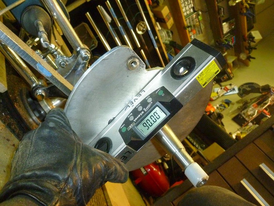
OK, no more entries, and FF gets the prize. I hold my digital level against the caliper mounting plate (or rotor) thusly:

Note that it reads 90 degrees, indicating that the plate is perpendicular to the ground. But this is only true if the spindle is straight out (parallel to the axle), which means the wheel and tire will be pointed straight ahead. If I move the plate and spindle a hair in either direction, the reading decreases:

...and this is due to caster; the plate tilts and the level shows it. If there was no caster, the level would always read 90 degrees.
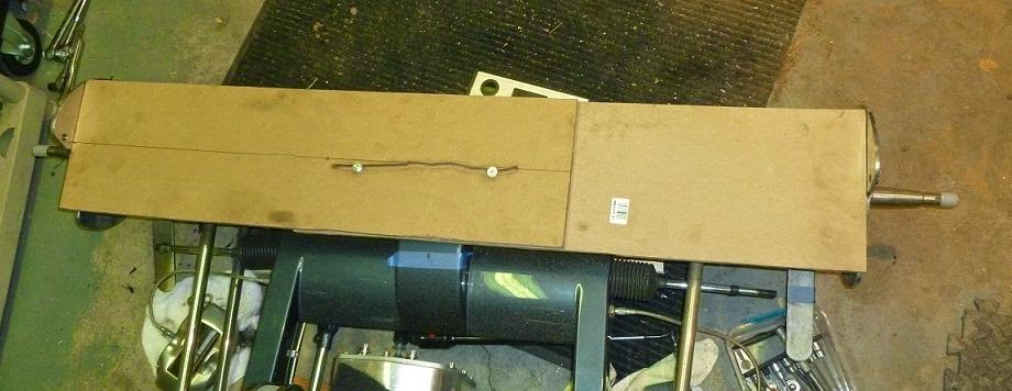
Here is another way to line 'em up:

It's just two pieces of MDF, cut with nice square ends and held together with a couple nuts and bolts and a slot to keep them parallel. Spread the boards to contact the plates or rotors. Tighten the nuts and the steering is ready to finish. Please refrain from snickering at the crooked slot; this is just a proof-of-concept, and all I had at hand was a RotoZip and a bit that didn't like MDF. But note that this seemingly crude method did as well as the level method.
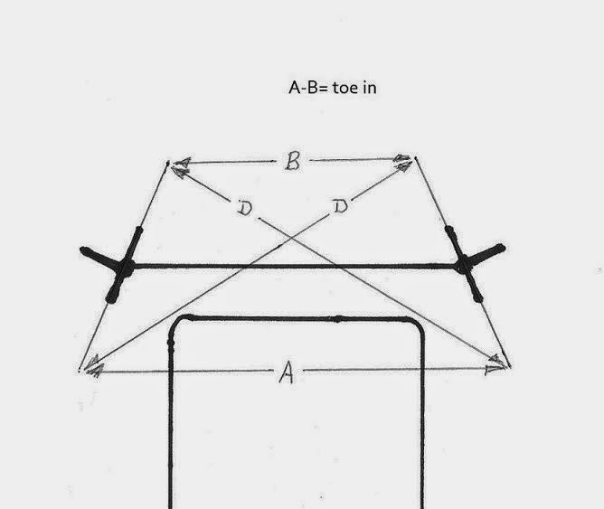
Returning to FF's arm and measuring method, I think that can also set toe:

Keep the diagonals D the same and that ensures the toe is equally applied to both sides.
Note that it reads 90 degrees, indicating that the plate is perpendicular to the ground. But this is only true if the spindle is straight out (parallel to the axle), which means the wheel and tire will be pointed straight ahead. If I move the plate and spindle a hair in either direction, the reading decreases:
...and this is due to caster; the plate tilts and the level shows it. If there was no caster, the level would always read 90 degrees.
Here is another way to line 'em up:
It's just two pieces of MDF, cut with nice square ends and held together with a couple nuts and bolts and a slot to keep them parallel. Spread the boards to contact the plates or rotors. Tighten the nuts and the steering is ready to finish. Please refrain from snickering at the crooked slot; this is just a proof-of-concept, and all I had at hand was a RotoZip and a bit that didn't like MDF. But note that this seemingly crude method did as well as the level method.
Returning to FF's arm and measuring method, I think that can also set toe:

Keep the diagonals D the same and that ensures the toe is equally applied to both sides.
roadmonster
Member
roadmonster
Member
It's super easy. It allows you to measure at axle height without frame or engine interference.
Screaming Metal
Active Member
Yea Ron and FluidFloyd.... who else knows besides us why there was a 2" offset in the Dragsters front axle....? hahaha....there was several folks that really took advantage of that little trick, when lining up at the stage/prestage lights....
fluidfloyd
Active Member
It use to be that only the T/F & F/C were allowed the 2" offset.Everything else was restricted to 1". I think Pro Stock and maybe comp can run the 2" deal now. Hell they might let everything from Jr. Dragsters to pit golf cars for all I know. I tend to believe the old Pro Comp TAD & Alcohol FC was restricted to 1" back in the '80s but opened up to the 2" allowance later. Probably because NHRA found it was easier to not have to police them which = Lazy!
Similar threads
- Replies
- 26
- Views
- 9K


