


You are using an out of date browser. It may not display this or other websites correctly.
You should upgrade or use an alternative browser.
You should upgrade or use an alternative browser.
CCR frame plans
- Thread starter 11290
- Start date
LumenAl
Member
RPM said:You all are doing better than me, I could not even find the pics on his Myspace.
here is direct link to page 51 of his photo album that has the pictures Ted is talking about...
Photos of Ted Brown Senior - MySpace Photos
Ted Brown
Member
Al, I think you are the best with these computers on this site.. hehe Rick sent me a program to resize my big pics, but damned if I can find it now.. Forgot where it went.. what can I say..") and Geroge, those so called bolts are not just studs, then have lock nuts behind those spaced mounts, and they are my eccentric adjustment bolts, (simular to Corvett rear adjustments)I also have pics up of those posted as well...
and Geroge, those so called bolts are not just studs, then have lock nuts behind those spaced mounts, and they are my eccentric adjustment bolts, (simular to Corvett rear adjustments)I also have pics up of those posted as well...
and Geroge, those so called bolts are not just studs, then have lock nuts behind those spaced mounts, and they are my eccentric adjustment bolts, (simular to Corvett rear adjustments)I also have pics up of those posted as well...GAB
Member
I don't think I described what I was asking about very well. Here is what it is:
I am familiar with the Corvette adjuster for the lower camber link. I made a pile of Corvette rear end mounting kits when the IRS's were in their first popularity. I've used the idea a couple of other places also. This one was for adjusting the axle and chain on a V-8 motorcycle. Worked well and was hidden with a cap.
I'm guessing that you were talking about the front attachment bolt for the radius rod????
blownt
Member
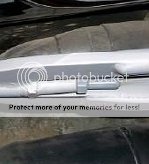
Eccentric adjustment bolts? What do they adjust? All I see is a rigid bushed rod end on the front end of the radius rods with a bolt going thru the bushing to the frame. I do not understand what the bolt, sleeve and nut adjust?????
http://img.photobucket.com/albums/v707/gbarnes/TedBrownRadiusRods.jpg
http://img.photobucket.com/albums/v707/gbarnes/TedBrownRadiusRods.jpg
Ted Brown
Member
Rick, I figured out that my ACDC photo program rules, so it does not like other stuff getting in the way, I reckon.. COMPUTERS, waaaay smarter than ME... need to go back to classes.... Thanks anyway...Rick said:Ted if you down loaded the program just right click on the pic and scroll down the drop down menu and you will see Resize Picture click that and you have four choices to resize them.Lf you lost the program let me know and i will resend.It is a Power Toy for Windows X.P
Ted Brown
Member
To adjust the length of the radius rod, for any small reasons that they may need to be changed, I loosen the back lock nut, turn the front bolt head, this moves the radius rod, in whatever direction you want, 1/4" in any direction off center line... clear? That makes for both ends, all 3 ends are done the same way, as the radius rods work in torsion as well as push, pull and lifting. everytime you go over a steep incline sideways at all. nothing to work itself looseblownt said:Eccentric adjustment bolts? What do they adjust? All I see is a rigid bushed rod end on the front end of the radius rods with a bolt going thru the bushing to the frame. I do not understand what the bolt, sleeve and nut adjust?????
http://img.photobucket.com/albums/v707/gbarnes/TedBrownRadiusRods.jpg
GAB
Member
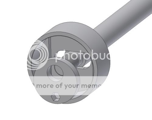
Here is a try at understanding what Ted is doing for an adjuster on the front of his radius rods. The stud that goes through the frame rail is turned as an eccentric to the main body of the adjuster. 1/4" off center that would give 1/2" of total movement.
I'm not sure that I understand his mention of the Corvette adjuster as they have a slot to keep the vertical height on the bolt that anchors the inner end of the camber link ??
Ted, am I anywhere close to what you have done? Inquiring minds want to know!
I'm not sure that I understand his mention of the Corvette adjuster as they have a slot to keep the vertical height on the bolt that anchors the inner end of the camber link ??
Ted, am I anywhere close to what you have done? Inquiring minds want to know!
akitagandy
Member
I understand now
Ted Brown
Member
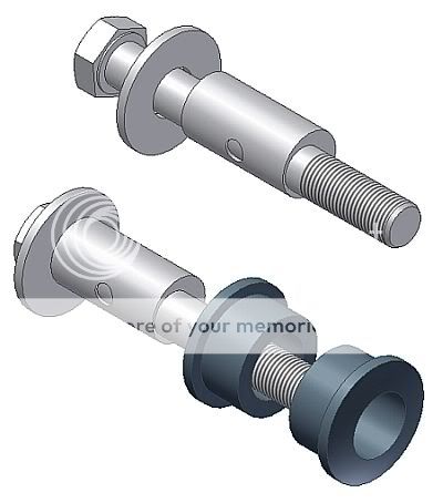
George, I have pics of my radius rod bolts, which I make, using 4" X 1/2" grade 5 bolts.. the adjustable unit, I make using a length of 3/4" solid stock, which I jeg drill to one side, leaving barely 1/16th material at one edge, I now drill a hole in that thin side, clean it all up, slide it on the bolt, weld up that 1.2: hole, to lock the unit in place, so it will not turn on the bolt, almost forgot, I install a large safety washer first, then the adjuster, weld, and use inside the large 4 bar bushings. You had the right idea, as I was bad at explaining it in the first place, LOVE your drawings, a pic is worth a thousand words, maybe more of mine. heheGAB said:Here is a try at understanding what Ted is doing for an adjuster on the front of his radius rods. The stud that goes through the frame rail is turned as an eccentric to the main body of the adjuster. 1/4" off center that would give 1/2" of total movement.
I'm not sure that I understand his mention of the Corvette adjuster as they have a slot to keep the vertical height on the bolt that anchors the inner end of the camber link ??
Ted, am I anywhere close to what you have done? Inquiring minds want to know!
 any better?
  IDEA!! Your idea may be even better, as this way, you could get even more adjustment with a larger unit... huuuuuummmmm... Thanks.. well on second thought, not so good, as I do not like BLIND bolt connections, really like to use LOCK nuts on the back sides of all my connections, if possible..
GAB
Member
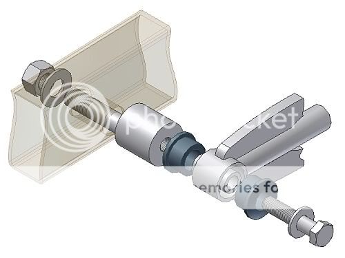
O.K., I think that I understand now...or at least i'll take another stab at it. :lol: Simpler and smaller is the name of the game. Try this one:
I don't know that I would worry that much about putting the bolt into a blind hole as shown in the other post. I doubt that the bolt would know whether it has a nut or a slug of bar stock on the other end of it....just the quality and the quantity of threads and the amount of torque that was applied. As you say, that's just me. Probably ought to worry more about the single shear situation.
One less mystery to ponder! :lol:
I don't know that I would worry that much about putting the bolt into a blind hole as shown in the other post. I doubt that the bolt would know whether it has a nut or a slug of bar stock on the other end of it....just the quality and the quantity of threads and the amount of torque that was applied. As you say, that's just me.
Probably ought to worry more about the single shear situation.One less mystery to ponder! :lol:
Ted Brown
Member
Geroge, you got it perfect this time, you must have looked at my pics.. hehe
Single shear, well my friend, many, actually ALL the AG/Super cars I built, never seemed to break any of that type of mount... and I am pretty sure they made a bit more HP than I do...
and you just may be right about using the bigger unit for the adjustment, and then use lock tite or just good grade lock washers on the main mounting bolts, or wire ties... Worth thinking about, Thanks again for the GREAT drawings... :lol:
PS, I have a new radius rod frame mount in mind to try, will/should work great in any position or angle, with NO BINDING... maybe I will have to get you to draw it..
jeffery
New Member
Ted Brown said:Geroge, you got it perfect this time, you must have looked at my pics.. hehe
Single shear, well my friend, many, actually ALL the AG/Super cars I built, never seemed to break any of that type of mount... and I am pretty sure they made a bit more HP than I do...
and you just may be right about using the bigger unit for the adjustment, and then use lock tite or just good grade lock washers on the main mounting bolts, or wire ties... Worth thinking about, Thanks again for the GREAT drawings...
PS, I have a new radius rod frame mount in mind to try, will/should work great in any position or angle, with NO BINDING... maybe I will have to get you to draw it..
Hi Ted,
I was looking at the CCR plans and from what i have seen on the plans the CCR radius rod bracket at one point the bracket is not a one unit piece unit its a 2 peice and the rad rods are different lengths.Am i reading this right?
Anyway i just got the frame welded together with 7018 rod and its straight and only 1/16th out on the diag measurments.Thats as close as i can get it with out making a jig to mount the frame pieces in. I also founf out that the jeep rearend is a dana rear with disc brakes so im going to use it and the follow your coil spring mount.
Thanks for the pictures and the ideas.going to make all the mounts myself, i thought about buying some of them but i think it will be more fun if i can REALLY say that i did the car myself (its a pride thing) i guess.
Vince
Ted Brown
Member
The frame radius rod mounting bracket is cut as 1 piece and bent in the middle, to match the radius rods, really not the correct way it should be done, those mounting bolts should be square with the axles. As everything rotates around that pivot point.. but with long radius rods, that movement is very small... It was easier to fab the radius rods that way, as now they fit either side, one will work anywhere, that is what happens when building a lot of cars, all the same, saves time and money, but when building for yourself, do it the right way....
jeffery
New Member
Ted,
I may have asked the wrong question but what i was wanting to find out from the plans for the CCR frame was why there is a difference on the plans for the attachment of the rad rods to the frame not the axles.On one sheet there is a single bracket attachment and on the other there is a bracket in two locations.Yes i agree that if they are all on one bracket on the frame then the rad rods can be used on either side.If im wrong let me know so i can understand this and make it right.
Thanks for you patience, Vince
Similar threads
