Ron Pope Motorsports                California Custom Roadsters               

T frame plans

RPM said:
Al you can download the file from here. Took me about 5 seconds to download.

Free file hosting by Savefile.com

I emailed them to yuo also.

Ron...

I need Ron (Youngster) to email me the CAD drawings from his CD... I can then export to PDF files or the DXF files you need... I can't convert a PDF file to a CAD or PXF file....
 
Hey Ron...have a question about the front x-member diameter. I plan on running a BBC...should I up the wall thickness or increase the diameter a bit?

I will be running a steel tub and the engine will be a mild big block(450 HP) but all of 600 lbs of iron!

Thanks!

Tommy
 
A 3/16" wall wouldn't hurt. I built one with a baby 396 in it and used a 10g tube 35 years ago and it's still running hard and strong.

Ron
 
Hi Ron, this is my first post here,I saw your plans(just what I was looking for) and I cant seem to get them to open! Is there aproblem??
Thanks in advance,George
 
hi lugnut and welcome, i just tried it and it works yet. being electronicly challenged i wouldn't want to send you off in the wrong direction. maybe al or mike will be able to help us out here.

Ron
 
tappin the 7/8 dom. I cut the tubing 1 inch longer for each end that needs threads. My lathe is too small so i use a right angle milwaukee electricians drill. I start with the smallest drill bit that will just start removing metal, then keep drilling and moving up in size until I get the right one for the tap. Then I change to the 5/8 bit and drill that extra 1 inch. then I tap the hole. That 5/8 hole will guide your tap in straight. when it's tapped, cut off that extra inch, redrill with the correct drill for the tap, ,, retap.. this gives good straight holes. And always use plenty of good tapping oil when drilling and tapping.
 
that's a great idea ted... that wall thickness do you use for the tubing? i grind a small flat on either side of the tube to hold on to.

Ron
 
ok... I'm lost.. I use tie rod ends on my radius rods where they attach to the frame and at the ends of my 4 link for the rear... but nothing is threaded into the frame... there is a special tapered flange and the Tie Rods are held in place with castle nuts... so where does the threaded bungs, made from 11/4" hex bar stock come in?
 
LumenAl said:
ok... I'm lost.. I use tie rod ends on my radius rods where they attach to the frame and at the ends of my 4 link for the rear... but nothing is threaded into the frame... there is a special tapered flange and the Tie Rods are held in place with castle nuts... so where does the threaded bungs, made from 11/4" hex bar stock come in?


I think they are talking about the front tie rod and drag link. If not, then I'm confused too.
 
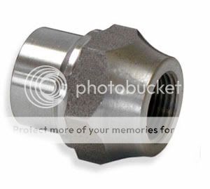
This is a weld in tube adapter from Mark Williams.
11221L.jpg

3/4"-16 to 1 1/4" x .095
For 1-1/4 x .095 tubing, hex wrench driver for 4-link. Threaded weld in tube adapters make fabricating linkage, struts or any other application that require joining a male rod end or threaded clevis to chromoly tubing a snap.
 
I am curious what size tube and tap/drill ya'll use to make the four link bars.
Thanks guys
vistin
 
All the tube stuff we make, we use 1" OD DOM with a .219" wall. Most is tapped with a 5/8-18 tap whoch seems to be standard to the T Bucket stuff. We do the radius rods, drag links and tie rods from this tube. We have seen a lot of the 7/8" tube radius rods bend.

In my pesonal bucket I use the same tube but it is drilled and tapped 3/4-16. It has a Moroso 4 link in it.
 
Hi Vistin,
I hope that my picture didnt cause any confusion. When Ted mentioned the hex type of weld in bung, I just posted a picture without looking at the size. RPM makes some very nice heavy-duty parts.
Total Performance plans show x .156 wall with a x 20 thread, while Speedway and CCR use 7/8 x .156 with a 5/8 x18 thread. Im not sure what Spirit is using.
Bill
 
i use 7/8 DOM 3/16 wall tubing. if you are using a ford tie rod end, you will need to open the 1/2 bore to 5/8 for the 11/16x18 or 11/16 for the 3/4x16 for the bushed ends. the 3/16 wall seems to work out just fine. i haven't had any problems with bending.

another reason i like the 7/8 is the 1/2" bore comes in handy when making other pieces where a 1/2" bolt is used.

the purpose of this set of plans is to give anyone a base to start from. please feel free to incorporate any changes you deem necessary to build your chassis to suit your needs. to date there are 12 chassis like this one on the road. the oldest is nearly 14 years old and is running a 396/turbo 400 with no problems.

one last word on the length of the rear hair pins. the longer they are, the more apt they are to bend. if you are building to teds or CCR's lengths, by all means use the 1" tubing. if you are using the steering box mount and the u-joints as a reference for your frame mounts, you can safely use the 7/8"tubing with 3/16" wall.

Ron
 
A couple of questions on Ron's plan:

1. I assume any bondo required on the frame rails would be applied after the frame is entirely built and just before priming. Correct?

2. Ron, for the front spring perch, let's see if I have this right. The perch brackets are slipped over the front tubular crossmember and then after the x-member is welded to the rails, the spring perch plate is welded to the the brackets after squaring.
 
hi craig...yes, wait till final assem to do you mud work. slide the front perch in place and tack it. that way if you have to move it after the suspension and motor is in you have only tacks to cut.

Ron
 

     Ron Pope Motorsports                Advertise with Us!     
Back
Top