


You are using an out of date browser. It may not display this or other websites correctly.
You should upgrade or use an alternative browser.
You should upgrade or use an alternative browser.
Complete Rewire Project
- Thread starter Indycars
- Start date

ellis8500
Member
Here's some info I found about a GM starter. As I mentioned the pull-in current for the starter solenoid is pretty high for a short time, hence the need for a relay. Even though the high current doesn't last but a few milliseconds, it can damage underrated switch contacts. This is also typical of Ford starters. Even 100 amp fuses can't handle the surge current. That's why you will never see a fuse in that circuit. Instead there will be a fuse-able link in the circuit. A fuse-able link is a short piece of wire 2 or 3 gauges smaller than the wire from the relay to the starter. If you are running 14 g to the starter, the link would be about 6 inches of 18 g wire covered with a flame retardant insulation. This, in effect, is a high current, very slow blow fuse.
Data for a GM PMGR PG260 1.7kw starter.
Max Power: 1.74KW
Max torqw: 21 Nm
Max Amp: 508amps
Solenoid Pull Current: 37.5amps
Solenoid Hold Current: 9.9amps
Data for a GM PMGR PG260 1.7kw starter.
Max Power: 1.74KW
Max torqw: 21 Nm
Max Amp: 508amps
Solenoid Pull Current: 37.5amps
Solenoid Hold Current: 9.9amps
ellis8500
Member
Regarding the ? fuses: Typically on these cars, unless you have some hi-watt sound system, 40 amp will be sufficient. Your highest load will be bright headlights; about 5 amps each. Your LED lights all together won't even be 1 amp. Ignition coil is about 3 amp. Your fan has it's own fuse. Fuel pumps vary. I have a Holley Might Mite 32 gph, less than 3 amps. Gauge power and lights less than 1 amp. I did blow my 10 amp headlight fuse so replaced with 15 amp and all is well.
Indycars
Well-Known Member
Here's some info I found about a GM starter. As I mentioned the pull-in current for the starter solenoid is pretty high for a short time, hence the need for a relay. Even though the high current doesn't last but a few milliseconds, it can damage underrated switch contacts. This is also typical of Ford starters. Even 100 amp fuses can't handle the surge current. That's why you will never see a fuse in that circuit. Instead there will be a fuse-able link in the circuit. A fuse-able link is a short piece of wire 2 or 3 gauges smaller than the wire from the relay to the starter. If you are running 14 g to the starter, the link would be about 6 inches of 18 g wire covered with a flame retardant insulation. This, in effect, is a high current, very slow blow fuse.
Data for a GM PMGR PG260 1.7kw starter.
Max Power: 1.74KW
Max torqw: 21 Nm
Max Amp: 508amps
Solenoid Pull Current: 37.5amps
Solenoid Hold Current: 9.9amps
So far from what I've read, I'm not a big fan of fusible links. What do others do in this situation??? But I'm still keeping an open mind. Sure seems there would be a fuse that would handle the inrush current, but still be only 50 amps. Maybe an ANL fuse type.
https://www.bluesea.com/products/5122/ANL_Fuse_-_50_Amp

I did add the relay to help with the load and take it off the starter switch. Up to version 10 now.

The inrush current on the starter solenoid is very brief and won't blow an ordinary fuse. I use a 15 amp fuse on my starter:
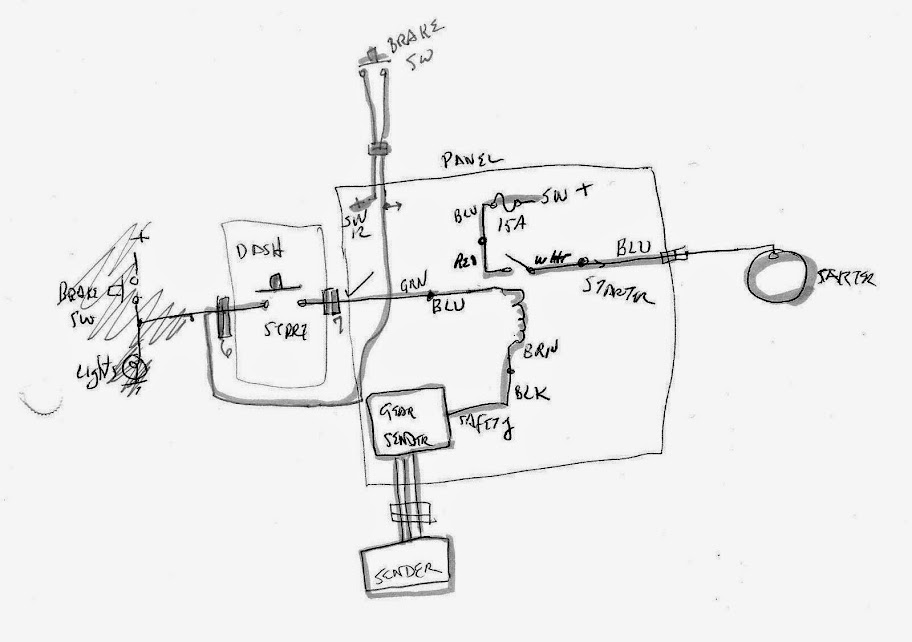
...one of these days I need to clean up my schematics. Note that I have it wired so the brake has to be on and the trans in N or P for the starter to work. This was prompted after I was standing outside and reached in to start the motor...and it was in Drive. And it started, and the big Hoosier yanked me down to the ground and tried to climb my back. I'll spare you the pic of how I looked after that, but here's my shirt:

...one of these days I need to clean up my schematics. Note that I have it wired so the brake has to be on and the trans in N or P for the starter to work. This was prompted after I was standing outside and reached in to start the motor...and it was in Drive. And it started, and the big Hoosier yanked me down to the ground and tried to climb my back. I'll spare you the pic of how I looked after that, but here's my shirt:
ellis8500
Member
Well, seems to be conflicting evidence regarding starter solenoid fuse. Some GM circuits show a 40 amp fuse, some show a fuse link. Ford says always use a fuse-able link. Guess it depends on your starter. Since I have a Ford engine I went with their advice. If you do use a fuse, make sure to have extras and a jumper if they all blow while you're away from home. It's your decision; just error on the side of reliability and safety.
Indycars
Well-Known Member
The inrush current on the starter solenoid is very brief and won't blow an ordinary fuse. I use a 15 amp fuse on my starter:
...one of these days I need to clean up my schematics. Note that I have it wired so the brake has to be on and the trans in N or P for the starter to work. This was prompted after I was standing outside and reached in to start the motor...and it was in Drive. And it started, and the big Hoosier yanked me down to the ground and tried to climb my back. I'll spare you the pic of how I looked after that, but here's my shirt:
Yikeessssss!!! .... I bet you felt alittle rough around the edges for a few days after that event !

Yes I'm having trouble making out that drawing. Looks like there are 3 switches involved. Is that a relay where the coil is and next to it, is a switch/contacts.
Indycars
Well-Known Member
Well, seems to be conflicting evidence regarding starter solenoid fuse. Some GM circuits show a 40 amp fuse, some show a fuse link. Ford says always use a fuse-able link. Guess it depends on your starter. Since I have a Ford engine I went with their advice. If you do use a fuse, make sure to have extras and a jumper if they all blow while you're away from home. It's your decision; just error on the side of reliability and safety.
I appreciate your open mindedness(is that a word), I don't want to offend anyone when I go a different direction.
I'm using a Power Master XS starter, but I can't see where the type or make of starter makes much difference.
ellis8500
Member
What you do with your project will offend no one here. Every one on this forum built a different car; no two are the same. How things are built depends on what you use in your project. As for starters, the design of the solenoid determines the current draw of the starter. As I've discovered, they vary from one manufacturer to the other. The best thing for you to do is call the manufacture's tech line and ask them what they recommend. As you will find here there is seldom ever one good answer to a question.
Yes, the coil and contacts are a relay. That's the way it's shown in schematics. Relays can have many contacts configurations. The one shown is a single-pole single-throw, or SPST, relay. Other common ones are single-pole double-throw (SPDT) and double-pole double-throw (DPDT).Yikeessssss!!! .... I bet you felt alittle rough around the edges for a few days after that event !
Yes I'm having trouble making out that drawing. Looks like there are 3 switches involved. Is that a relay where the coil is and next to it, is a switch/contacts.
You know, I use one of the small gear-reduction starters, which might not have as much inrush current. I like that starter, it's half the weight and size of a stock starter and really spins the motor.
Indycars
Well-Known Member
Thanks, that's the ultimate comment, it most greatly appreciated.This has been a very educational thread.
Indycars
Well-Known Member
I broke my instrument schematic into two drawings, one for the SpeedHut gauges and one for my AEM gauges. SpeedHut consists of Tachometer, Speedometer and Clock. The speedometer has the turn indicators and bright headlight indicator internal to the gauge. The speedometer works off of GPS, which allows me to do several things, two of which is 1/4 miles times and 0-60 times. Even the gauges are going to be fun to play with!!! ")


 in my cold little garage.
Indycars
Well-Known Member
Ok, good. Thought maybe I had lost you two guys support. I know you are not obligated to help me, but was hoping I would be able to run a few more schematics by you two and catch as many mistakes as possible. I've never rewired a car before and I want to do it from scratch without burning down the car.

Similar threads
- Replies
- 17
- Views
- 5K
