


You are using an out of date browser. It may not display this or other websites correctly.
You should upgrade or use an alternative browser.
You should upgrade or use an alternative browser.
Complete Rewire Project
- Thread starter Indycars
- Start date

Yes, it's amazing how even a simple electrical system can have so many wires.View attachment 11208
It's not the amount of wires, it's about how simple it is to repair if need be. Color coding, ease of access, and ability to repair on the spot, so to speak without anyone but YOU doing it. EFI and anything computerized, not everyone can diagnose and repair, not even the owners of most of them, so, simpler is better for most.
Indycars
Well-Known Member
Back on page 6, I posted this graphic, then there is reality.

Some of my components mounting holes are underneath the seat back cushion
making it hard to tighten screws back there as you can see from the photo below.

So I made this bracket to pin the back side of the AQ-1 while I use the two front
screws to finish the mounting. I will mount the bracket before I slip the 1/4 inch
plate into place with most components and bracket already mounted. If needed I
can easily remove the AQ-1 by itself without removing the entire plate. Might
consider more brackets for other components, time will tell.


I'm using a 1/4 inch Acrylic plate for mounting, instead of going direct to the floor.
The advantage is drill and mounting components while in FULL view and laying on
the floor for best access. This is where I'm at now with the right side (battery side)
almost finished mounting, notice the screws holding components in place. Still thinking
and circling the left side, there might be some changes !!!

Cost of the 1/4" thick Acrylic plate was $30 from a local supplier.
Some of my components mounting holes are underneath the seat back cushion
making it hard to tighten screws back there as you can see from the photo below.
So I made this bracket to pin the back side of the AQ-1 while I use the two front
screws to finish the mounting. I will mount the bracket before I slip the 1/4 inch
plate into place with most components and bracket already mounted. If needed I
can easily remove the AQ-1 by itself without removing the entire plate. Might
consider more brackets for other components, time will tell.
I'm using a 1/4 inch Acrylic plate for mounting, instead of going direct to the floor.
The advantage is drill and mounting components while in FULL view and laying on
the floor for best access. This is where I'm at now with the right side (battery side)
almost finished mounting, notice the screws holding components in place. Still thinking
and circling the left side, there might be some changes !!!
Cost of the 1/4" thick Acrylic plate was $30 from a local supplier.
Indycars
Well-Known Member
Is there any reason why I cannot use different size pins in the same Deutsch DT connector? I have 12, 14 and 16 gauge wire coming out of the steering column, that means two different size pins. I will have to use a different connector than a Deutsch DT for the 12 gauge wire.
The connector will be under the car, so I do like that the Deutsch has a good environmental seal.
The connector will be under the car, so I do like that the Deutsch has a good environmental seal.
From my brief look (never used them), it's complicated. They have solid contacts or stamped contacts. And there are different "series" of connectors; DT, DTM, DTP. Do you have a series in mind? But I get the feeling that a connector will only accept one contact size, but a given contact can accommodate a range of wire sizes. And I don't know what tool is used to crimp. Let us know what you find.
Indycars
Well-Known Member
From my brief look (never used them), it's complicated. They have solid contacts or stamped contacts. And there are different "series" of connectors; DT, DTM, DTP. Do you have a series in mind? But I get the feeling that a connector will only accept one contact size, but a given contact can accommodate a range of wire sizes. And I don't know what tool is used to crimp. Let us know what you find.
I have solid pins and sockets, that seem to be the same size on the mating ends. They seem to have the same insertion force and are within .001 inches of diameter of each other. The only difference is the size of wire that can be crimped in the barrel. So my take on this is either pin/socket will work within the same connector
I'm using the DT series of connectors, you know the same ones that NASCAR uses. Or so I've read anyway.

Here is a video to show how the connectors are assembled. I could take photos of every step, but the video shows it much better than anything I can do.
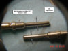
This is what I ended up with, the yellow wire is 12 gauge and can't go thru the DT connector.

I bought these crimpers and so far they have worked perfectly....very happy with them. Plus I only need one of them for most of my work, it does all three sizes of 14-16-18 gauges. The second crimper does 20-22 gauges. Much less wondering where in the hell I put that tool, it was just in my hand 15 seconds ago.

http://www.toolaid.com/content/deutsch-terminals-service-kit

Attachments
James C
Member
Have you thought about using one of these? http://shoraipower.com/lfx36l3-bs12-p130 1/3 the weight and more CCA.
Indycars
Well-Known Member
Have you thought about using one of these? http://shoraipower.com/lfx36l3-bs12-p130 1/3 the weight and more CCA.
No, didn't know about that battery. But I am using the Odyssey PC-680 battery, it's of similar size.

Indycars
Well-Known Member
I've been pulling wires thru the frame after drilling a 3/4" holes right under the
headlights. I'm running separate wires up each side of the frame to the headlights,
when I could run up one side and then cross over to the other side with a parallel
circuit for the other side. Also I'm running grounds all the way back to the fuse
panel in stead of using the frame. IIRC .....Steel has about 10 times the resistance
of copper.
I ran 12 gauge wire to the headlights, but the three wires would not fit thru the hollow
bolts that feed the headlight bucket. I started drill with 9/32 inch bit and ended with
11/32 inch bit before three 12 gauge wires and heat shrink would fit thru the hollow
bolts. I think the bolt is still substantial enough to hold up to driving. I guess most
people run 14 or 16 gauge wire to the headlights.


Added labels to each wire inside the headlight bucket. On the back of each headlight
is a Sharpie label to match, therefore only an idiot like me could get it wrong.


Same headlight wires where they come into the relays under the seat.

I'm updating the wiring schematics as I run the wires to reflect the color and
size of wire.

I'm using this to to do my labels.

headlights. I'm running separate wires up each side of the frame to the headlights,
when I could run up one side and then cross over to the other side with a parallel
circuit for the other side. Also I'm running grounds all the way back to the fuse
panel in stead of using the frame. IIRC .....Steel has about 10 times the resistance
of copper.
I ran 12 gauge wire to the headlights, but the three wires would not fit thru the hollow
bolts that feed the headlight bucket. I started drill with 9/32 inch bit and ended with
11/32 inch bit before three 12 gauge wires and heat shrink would fit thru the hollow
bolts. I think the bolt is still substantial enough to hold up to driving. I guess most
people run 14 or 16 gauge wire to the headlights.
Added labels to each wire inside the headlight bucket. On the back of each headlight
is a Sharpie label to match, therefore only an idiot like me could get it wrong.
Same headlight wires where they come into the relays under the seat.
I'm updating the wiring schematics as I run the wires to reflect the color and
size of wire.
I'm using this to to do my labels.
 .... talk about overkill.... AND relays ?????!!!!
Indycars
Well-Known Member
I figured I might want to add Halogen lights at some point, so that's 100 watts. Not sure if that's for the pair or each, so I assumed the worst making 200 watts possible.
I = P/E = 200/13.8 = 14.5 amps
Looking at the chart below for 15 amps / 15 feet, it shows 14 gauge wire, so I went to the next largest gauge at 12 gauge.

So I did have some reasoning for my choice, although it really hinges on the assumption of 100 watts per headlight.
I = P/E = 200/13.8 = 14.5 amps
Looking at the chart below for 15 amps / 15 feet, it shows 14 gauge wire, so I went to the next largest gauge at 12 gauge.
So I did have some reasoning for my choice, although it really hinges on the assumption of 100 watts per headlight.
mountainman
Member
Just a quick thought and I may be missing something but you stated in post # 131 that you ran separate wires to each headlight. So, if you go to the Halogens, each wire would only have a 100 watt load, not 200. That cuts amps in half and would only require 18 ga per the above chart. Correct me if I am wrong......my wife does it all the time.
Indycars
Well-Known Member
Yes you are right I did say that!
Now for what actually happened. The screw clamp for the relay would not hold two 12 gauge wires. So I soldered a tee bringing both sides together under the floor and just before it comes thru the hole in the floor. So another words, the last 12 inches is a single 12 gauge wire to the relay.
Damn I should have used a 10 gauge after the tee!")
")
Now for what actually happened. The screw clamp for the relay would not hold two 12 gauge wires. So I soldered a tee bringing both sides together under the floor and just before it comes thru the hole in the floor. So another words, the last 12 inches is a single 12 gauge wire to the relay.
Damn I should have used a 10 gauge after the tee!
Indycars
Well-Known Member
Damn, Indy, that looks so good I want to redo my car now with the Deutsch connectors. Is there no limit to our madness? I hope not.
Don't worry PotvinGuy, I will cut way back on the quality of the wiring so you can get back on the road this summer !!!
I hope there is no limit, when that day comes I'm hanging up my spurs.
I tell you why I like the Deutsch connectors... I don't have as much to remember during crimping and not as much inventory to keep on hand. The Deutsch has only on the PIN or SOCKET when you crimp, then push it in from the back side. Install Wedgelock from the front and you are done. I did this under the car and on my back in a somewhat tight spot. Notice it also has a way to mount the connector to a stationary surface, so it's not flopping around unlike the Weather Pack.


The Weather Pack takes two crimps, plus you need to remember to install the seal first before crimping.


All this I come to understand after working with the Deutsch connector, and not before the experience.
Last edited:
Similar threads
- Replies
- 17
- Views
- 5K
